


25
W415-0810 / 06.11.09
FOR YOUR SAFETY READ BEFORE LIGHTING:
Ɣ
This appliance is equipped with a pilot which must be lit by hand while following these instructions exactly.
Ɣ
Before operating smell all around the appliance area for gas and next to the floor because some gas is heavier than air and will settle on the floor.
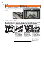
Ɣ
Use only your hand to push in and turn the gas control knob. Never use tools. If the knob will not push in and turn by hand, do not try
to repair it. Call a qualified service technician. Force or attempted repair may result in a fire or explosion.
Ɣ
Do not use this appliance if any part has been under water. Immediately call a qualified service technician to inspect the appliance
and replace any part of the control system and any gas control which has been under water.
Ɣ
Do not try to light any appliance.
Ɣ
Do not touch any electric switch; do not use any phone in your building.
Ɣ
Immediately call your gas supplier from a neighbour’s phone. Follow the gas supplier’s instructions.
Ɣ
If you cannot reach your gas supplier, call the fire department.
When lighting and re-lighting, the gas knob cannot be turned from pilot to off unless the knob is depressed.
$
STOP! Read the above safety information on this label.
%
Set the thermostat to lowest setting.
&
Turn off all electric power to the appliance.
'
Open the control door. Turn the gas knob clockwise to off.
(
Wait five (5) minutes to clear out any gas. If you smell gas including near the floor, STOP! Follow “B” in the above safety information
on this label. If you don’t smell gas go to the next step.
)
Find pilot located in front of the back log.
G.
Turn gas knob counter-clockwise to pilot.
H.
Depress and hold gas knob while lighting the pilot with the push button ignitor. Keep knob fully depressed for one minute, then
release. If pilot does not continue to burn repeat steps 3 through 7.
,
.
With pilot lit, turn gas knob counter-clockwise to on. When the pilot has been turned off,
ignition of the main burner may be delayed from 1-2 minutes. When the pilot has been left
burning, ignition of the main burner should occur almost immediatley.
-
.
If equipped with remote on-off switch, main burner may not come on when you turn the valve to on. Remote switch must be in
the on position to ignite burner.
K.
Turn on all electric power to the appliance.
A.
Turn off all electric power to the appliance if service is to be performed.
%
.
Push in gas control knob slightly and turn clockwise to off. Do not force.
WHAT TO DO IF YOU SMELL GAS:
LIGHTING INSTRUCTIONS:
TO TURN OFF GAS
,IDSSOLDQFHVKXWVRIIGRQRWUHOLJKWXQWLO\RXSURYLGHIUHVKDLU
.
,IDSSOLDQFHNHHSVVKXWWLQJRIIKDYHLWVHUYLFHG
.
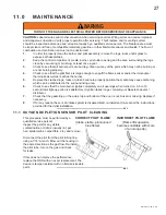
K
HHSEXUQHU
DQGFRQWUROFRPSDUWPHQWFOHDQ
.
When lit for the first time, the appliance will emit a slight odour for a few hours. This is a normal temporary condition caused by the curing
of the logs and the “burn-in” of internal paints and lubricants used in the manufacturing process and will not occur again. After extended
periods of non-operation such as following a vacation or a warm weather season, the appliance may emit a slight odour for a few hours.
This is caused by dust particles burning off. In both cases, open a window to sufficiently ventilate the room.
GA
6
K
12%
2;<
G
(1'(3/(7,216(1625
GA
6
K
12%
A
72))
L
FF
O
P
I
N
O
L
O
T
IH
O
P ILOT
47.1
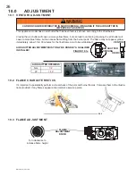
9.0 OPERATION
IF YOU DO NOT FOLLOW THESE INSTRUCTIONS EXACTLY, A FIRE OR EXPLOSION MAY RESULT
CAUSING PROPERTY DAMAGE, PERSONAL INJURY OR LOSS OF LIFE.
!
WARNING
Содержание GVF40N
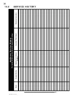
Страница 35: ...35 W415 0810 06 11 09 15 0 NOTES 44 1 ...
Страница 36: ...36 W415 0810 06 11 09 44 1 ...


