


33
W415-0810 / 06.11.09
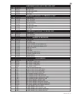
SYMPTOM
Pilot goes out while
standing; Main burner
is in ‘OFF’ position.
Flames are consis-
tently too large or too
small. Carboning
occurs.
Carbon is being
deposited on logs or
combustion chamber
surfaces.
Exhaust fumes
smelled in room,
headaches.
Remote wall switch is
in “off” position; main
burner comes on
when gas knob is
turned to “ON”
position.
PROBLEM
TEST SOLUTION
Gas piping is undersized.
Pilot flame is not large enough.
Unit is over-fired or under-fired.
Air shutter improperly adjusted.
Air shutter has become blocked.
Flame is impinging on the logs or
combustion chamber.
Not enough combustion air.
Not enough ventilation air.
Flame is impinging on the logs or
combustion chamber.
Wall switch is mounted upside
down.
Remote wall switch is grounding.
Remote wall switch wire is
grounding.
Faulty valve.
- Turn on all gas appliances and see if pilot flame flutters,
diminishes or extinguishes, especially when main burner
ignites. Monitor appliance supply working pressure.
- Check if supply piping size is to code. Correct all undersized
piping.
- ODS Burner requires checking.
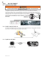
- Check pressure readings:
Inlet pressure can be checked by turning screw (A) counter-
clockwise 2 or 3 turns and then placing pressure gauge tubing
over the test point. Check with burner operating on “HI”.
Gauge should read 7” (minimum 4.5”) water column for
natural gas or 13” (11” minimum) water column for propane.
Outlet pressure can be checked the same as above using
screw (B). Check with burner operating on “HI”. Gauge should
read 3.5” water column for natural gas or 10” water column for
propane.
AFTER TAKING PRESSURE READINGS, BE SURE TO
TURN SCREWS CLOCKWISE FIRMLY TO RESEAL. DO
NOT OVERTORQUE.
Leak test with a soap and water solution.
- Return air shutter to specified opening, see “VENTURI
ADJUSTMENT” section.
- Ensure air shutter opening is free of lint or other obstructions.
- Check that the logs are correctly positioned.
- Open air shutter to increase the primary air. See air shutter
openings, page 15.
- Check the input rate: check the manifold pressure and orifice
size as specified by the rating plate values.
- Increase fresh air supply. (Use one of the methods described
in ANSI Z223.1 Section 5.3 or the applicable local code.)
- Increase fresh air supply. (Use one of the methods described
in ANSI Z223.1 Section 5.3 or the applicable local code.)
- Check that the logs are correctly positioned.
- Open air shutter to increase the primary air. See air shutter
openings, page 15.
- Check the input rate: check the manifold pressure and orifice
size as specified by the rating plate values.
- Reverse.
- Replace.
- Check for ground (short); repair ground or replace wire.
- Replace.
P
I
A
B
PILOT
N
O
L
O
T
H I
L O
FF
O
42.4_2
Содержание GVF40N
Страница 35: ...35 W415 0810 06 11 09 15 0 NOTES 44 1 ...
Страница 36: ...36 W415 0810 06 11 09 44 1 ...


