


10
WS-415-090 / 04.03.00
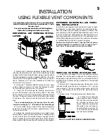
Spacers are attached to the 4" inner flex liner at prede-
termined intervals to maintain a 1-1/4" air gap to the 7"
outer liner. These spacers must not be removed.
7.
If more liner needs to be used to reach the fireplace,
follow the same procedure as found in
EXTENDED HORI-
ZONTAL AIR TERMINAL INSTALLATION.
The vent system
must be supported approximately every 3 feet for both ver-
tical and horizontal runs. Use Napoleon support ring as-
sembly
GA-GD-010.370
or equivalent noncombustible
strapping to maintain the minimum clearance to combus-
tibles as well as to prevent sagging.
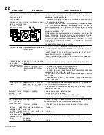
FIREPLACE VENT CONNECTION
1.
Install the 4
inch diameter alu-
minum flexible
liner to the fire-
place. Secure with
3 screws and flat
washers. Seal the
joint and screw
holes using the
high temperature
sealant provided.
2.
Install the 7 inch diameter aluminum flexible liner to
the fireplace. Attach and seal the joints.
3.
Move the fireplace into position. The two holes in the
fireplace base located behind the lower louvre assembly
may be used to attach the fireplace to the floor using
screws.
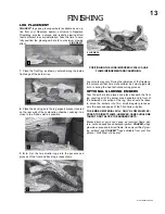
5.
Remove nails
from the shingles,
above and to the sides
of the chimney. Place
the flashing over the air
terminal and slide it
underneath the sides
and upper edge of the
shingles.
Ensure that the air terminal is properly centered within the
flashing, giving a 3/4" margin all around. Fasten to the roof.
Do
not
nail through the lower portion of the flashing. Make
weather-tight by sealing with caulking. Where possible,
cover the sides and top edges of the flashing with roofing
material.
6 .
A p p l y a h e a v y
bead of weatherproof
c a u l k i n g 2 i n c h e s
a b o v e t h e f l a s h i n g .
Slide the storm collar
around the air terminal
and down to the caulk-
ing. Tighten to ensure
that a weather-tight
seal between the air
terminal and the collar is achieved. Attach the other storm
collar centered between the air intake and the air exhaust
slots onto the air terminal. Tighten securely. Attach the ver-
tical rain cap.
FIGURE 15
FIGURE 16
FIGURE 17
For safe and proper operation of the fireplace,
follow the venting instructions exactly.
For optimum performance, it is recommended
that all horizontal runs have a minimum ¼ inch
rise per foot.
The vent system must be supported approximately every 3
feet for both vertical and horizontal runs. Use Napoleon
vent spacers
WS-615-33
or equivalent every 3 feet and ei-
ther side of each elbow to maintain the minimum 1¼" clear-
ance between the outer and inner vent pipes. Use Napo-
leon support ring assembly
GA-GD-010.370
or equivalent
noncombustible strapping to maintain the minimum clear-
ance to combustibles for both vertical and horizontal runs.
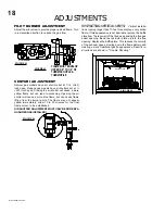
INSTALLATION
USING RIGID VENT COMPONENTS
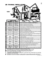
HORIZONTAL AIR TERMINAL INSTAL-
LATION
1.
Move the fireplace into position. Measure the vent length
required between terminal and fireplace taking into account
the additional length needed for the finished wall surface
and any 1¼" overlaps between venting components.
2.
Apply high temperature sealant to the outer edge of the
4" inner collar of the fireplace. Attach the first vent compo-
nent and secure using 3 self tapping screws. Repeat us-
ing 7" piping.
3.
Holding the air terminal (lettering in an upright, read-
able position), insert into both vent pipes with a twisting
motion to ensure that both the terminal sleeves engage
into the vent pipes and the sealant. Secure the terminal to
the exterior wall and make weather tight by sealing with
caulking (not supplied).
The air terminal mounting plate may be recessed
into the exterior wall or siding by 1½", the depth
of the return flange.
FIGURE 18
Содержание GD27 - N
Страница 23: ...23 WS 415 090 04 03 00 NOTES...


