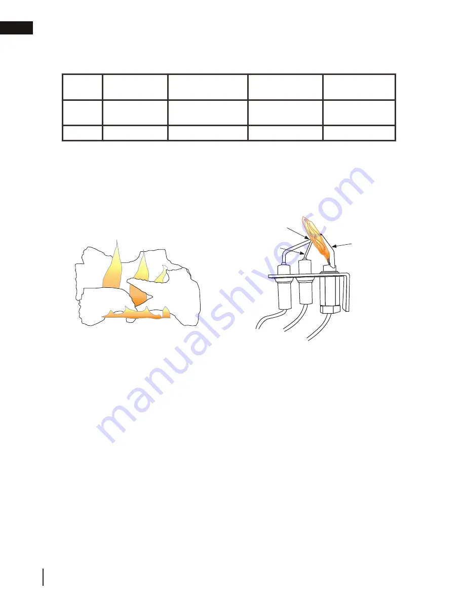
8.4 fl ame characteristics
FLAME MUST ENVELOP
UPPER 3/8” (9.5mm) TO
1/2” (12.7mm) OF FLAME
SENSOR
PILOT
BURNER
FLAME
SENSOR
SPARK MODULE
It’s important to periodically perform a visual check of
the pilot and burner flames. Compare them to the
illustration provided. If any flames appear abnormal,
call a service person.
Prior to pilot adjustment, ensure that the pilot assembly has not been painted. If overspray or painting of
the pilot assembly has occurred remove the paint from the pilot assembly, or replace. Fine emery cloth or a
synthetic scrub pad (such as Scotch-Brite™) can be used to remove the paint from the pilot hood, electrode
and fl ame sensor.
*Maximum inlet pressure not to exceed 13”
Pressure
Natural Gas
(inches)
Natural Gas
(millibars)
Propane
(inches)
Propane
(millibars)
Inlet
*7”
(minimum 4.5”)
17.4mb
(minimum 11.2mb)
13”
(minimum 11”)
32.4mb
(minimum 27.4mb)
Outlet
3.5”
8.7mb
10”
24.9mb
W415-2347 / C / 09.21.20
EN
36
adjustment
Содержание Bayfield GDS25NW-1
Страница 49: ...EN W415 2347 C 09 21 20 49 notes...
Страница 99: ...W415 2347 C 09 21 20 99 notes FR...


