background image

9

W415-0512 / B / 11.15.05

3.


The access panel can be removed by taking out the 8

#10 self taping screws. A 5/16" nut driver will be required to

complete this job. Unplug wires from the thermal switch

on the panel. See 

FIGURE 15.

4.

 Remove the securing wingnut from the blower mounting

bracket, slide the bracket to the right and rotate the left side

of the assembly out of the cavity to clear the blower motor.

Disconnect the two wires from the blower motor. Remove

the ground wire from the blower mounting bracket, then

the assembly can  be taken out of the rear cavity through

the access door opening.

5.


Remove the 3 screws that hold the blower to the mount-

ing bracket. Service or replace the blower as required.

6.


Reinstall the blower assem-

bly making sure the blower

bracket is seated under the se-

curing tab. 

FIGURE 16

. Reattach

the wire connectors. 

FIGURE 17

.

7.

 Replace the gasket on the ac-

cess door. To replace the ac-

cess panel, reverse Step 3 .

8.

 Replace the bricks into the

firebox. Reinstall the door.

1.


Turn off all electrical power to the insert. Remove the

glass door and set aside in a safe place.

2.

 Remove the two screws from the outer edge of the side

panel(s).

3.

 Push the side panel toward the door and pull away from

the insert, releasing the panel from the keyed slot.

4.

 Service or replace the blower(s) as required.

5.

 Re-install the side panel(s) by reversing the procedure.

FIGURE 16

HEAT

SENSOR

G

B

W

FIGURE 18

SECURING

TAB

WINGNUT

GROUND STUD

WIRES

FIGURE 17

1401 BLOWER SERVICE OR REPLACEMENT

1150 BLOWER INSTALLATION

1150 FEATURES

FIGURE 20

Wood

Storage

(intended for

short term use)

Pot

Fender

FIGURE 19

1.

 Remove the

knock-out from

the back of the

fireplace.

2. 

Install the blower

and housing as

shown using the 4

screws supplied.

3.

 Loosen the thermodisc bracket (2 screws) and slide the

bracket forward until the thermodisc is touching the rear

firebox and secure.

Remove the screw, as illustrated,
from the preferred side of the stove
rear. Secure the lid lifter hook, as
illustrated, facing out to the side, or
bend it towards the back.

LID LIFTER

HOOK

Содержание 1100C

Страница 1: ...lothing etc placed too close can catch fire Adults and especially children should be alerted to the hazards of high surface temperatures and should stay away to avoid burns or clothing ignition Keep y...

Страница 2: ...7 2 m c 9 6 n i 7 2 m c 9 6 n i 7 2 m c 0 8 n i 2 1 1 3 G N I H S A L F D N I H E B H T P E D m c 4 5 o t 2 4 n i 1 2 o t 2 1 6 1 m c 7 3 n i 2 1 4 1 O T E N I L R E T N E C E U L F R A E R m c 1 5 6...

Страница 3: ...essive heat abrasive and chemical cleaners nor chipping on porcelain enamel parts nor any venting components used in the installation of the fireplace In the first year only this warranty extends to t...

Страница 4: ...feature of the stove is utilized you should never experience a shortage of combustion air If you choose not to utilize outside air and experience draft or smoking problems you may need to open a door...

Страница 5: ...e installed with the crimped end toward the stove This will ensure that the moisture which condenses from the burning wood will flow back into the fire chamber Each joint in the stove pipe must be se...

Страница 6: ...nstall a rain cap at the top which will not impede the smoke exhaust The chimney must be supported at the ceiling or roof so that its weight does not rest on the stove UNDERSIDE OF JOIST FIRESTOP SPAC...

Страница 7: ...icient enough to allow the connector to fit under the noncombustible facing The fireplace and chimney must be constructed in accord ance with all national and local building code standards HINT FOR IN...

Страница 8: ...mper may be removed to install the chimney liner 7 Circulating air chambers i e in a steel fireplace liner or metal heat circulator shall not be blocked 8 Means must be provided for removal of the ins...

Страница 9: ...nel reverse Step 3 8 Replace the bricks into the firebox Reinstall the door 1 Turn off all electrical power to the insert Remove the glass door and set aside in a safe place 2 Remove the two screws fr...

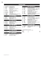
Страница 10: ...x 4 1 2 x 4 1 2 4 1 1 4 x 4 1 2 x 9 5 1 1 4 x 2 1 2 x 4 1 2 6 1 1 4 x 1 1 2 x 4 1 2 7 1 1 4 x 4 1 2 x 9 light weight 8 1 1 4 x 2 1 4 x 9 9 1 1 4 x 2 1 4 x 6 1 8 10 Fibre baffle 9 x 1 x 12 11 Fibre ba...

Страница 11: ...to keep your house free of carbon monoxide in case of a downdrafting chimney or an internal negative pressure The first fire s in your unit will be difficult to get going and keep going with little am...

Страница 12: ...ctivate or relocate the smoke detector When loading the stove ensure that the two upper fibre baffles are not lifted up and off their ledge For maximum efficiency when the stove is thoroughly hot load...

Страница 13: ...hem once a year Re place any broken bricks When wood is burned slowly it produces tar and other or ganic vapours which combine with expelled moisture to form creosote These vapours condense in the rel...

Страница 14: ...ass Ideal lengths of wood are approximately 12 for EPA 1100 1100C 1100L 1150 and 1101 16 1 2 for EPA1400 1400L and 1401 and 21 for EPA 1900 1 Remove cast top 2 Pull pin from top door hinge It is impor...

Страница 15: ...55 W135 0237 CAST PEDESTAL BASE 56 W135 0238 CAST ASH TRAY 57 W325 0040 HANDLE LID LIFTER 22 W090 0016 BRICK 5 23 W090 0017 BRICK 6 28 CL28 BLACK CANOPY LOUVRES 29 CL28G GOLD PLATED CANOPY LOUVRES 30...

Страница 16: ...ENTAL CAST IRON LEGS BRUSHED STAINLESS STEEL 1100 COMPONENTS 1100L COMPONENTS 1400 COMPONENTS 1101 COMPONENTS 1401 COMPONENTS 1150 COMPONENTS 66 EP62 1 VARIABLE SPEED BLOWER 77 EPA RK SOLID BRASS RAIL...

Страница 17: ...0512 B 11 15 05 59 15 16 18 17 19 16 57 2 32 12 10 14 30 33 74 31 44 84 83 73 72 76 63 64 Z P Ins ClassB 115V 60Hz 46W EM3030L 167 zr 2 073 SEL 81 66 1 46 77 40 38 39 58 65 55 56 48 49 85 47 52 53 54...

Страница 18: ...18 W415 0512 B 11 15 05 Wolf Steel Fireplace Service History This fireplace must be serviced annually depending on usage Date Service Technician Name Service Performed Special Concerns Dealer Name...

Страница 19: ...19 W415 0512 B 11 15 05 NOTES...

Страница 20: ...20 W415 0512 B 11 15 05 NOTES...

Отзывы: