background image

L

 NAPCO Security Systems  

Freedom F-64 Programming Instructions 


Page 43


WI1502A  9/06 


TOUCHPAD MENU MODE 

The Touchpad can provide access to a wide assortment 
of utility functions, each displayed on the Touchpad LCD 
window in a prompting “YES/NO” format.  This Touchpad 
menu is not necessary for panel programming, but is in-
cluded here for reference.   
 

TYPICAL USER

:  Homeowner.   

TYPICAL INTERFACE

:  Touchpad only.   

HOW TO ENTER

:  At the installed Touchpad, insert the 

Master I-FOB and press 

MENU 

to enter.  All mes-

sages in the 

Touchpad Menu Mode 

are listed be-

low, but some messages may not appear in the 
Touchpad display unless a User or Master I-FOB is 
inserted in the Touchpad; if the required condition is 
not present; or if the F-64 control panel is configured 
in such a way as to remove the message from this 
Menu.  For example, “

DISPLAY ZN FAULTS Y/N

” 

will only display if zones are faulted.  With each mes-
sage, press 

YES 

to proceed with the change or 

NO 

to skip to the next selection.  

Note:

  Highlighted mes-

sages are sub-menu selections. 

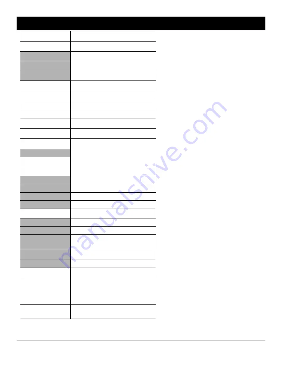
ALL MESSAGES  

IN MENU 

NOTES 

ENTER BYPASS  
MENU              Y/N 

When bypassing a zone, press 

BYPASS 

to enter this menu. 

DISPLAY  
ZN DIRECTORY 

      Y/N 

Allows individual zones to be bypassed.  Press 

Yes 

or 

No 

to 

scroll through zone list. 

BYPASS 
OPEN ZONES? 

       Y/N 

Disables monitoring of all faulted zones EXCEPT the PRI-

MARY Touchpad door. 

DISPLAY 
ZN BYPASSED 

       Y/N 

Scrolls list of bypassed zones (cannot unbypass from this 

selection). 

ACTIVATE 
CHIME             Y/N 

When activated, this selection reads "

DEACTIVATE 

CHIME Y/N

". 

CHANGE KEYPAD  
BEEP VOLUME       Y/N 

Selections are LOW (default), MED, MED-HIGH, HIGH, and 

OFF (tactile or entry warning only). 

CHANGE VOICE 
VOLUME            Y/N 

Selections are LOW, MED, MED-HIGH (default), HIGH, 

OFF (voice prompt volume). 

ACTIVATE 
SIREN TEST        Y/N 

Press 

YES 

to activate burg relay output for 2 seconds. 

DISPLAY 
FIRE ALARM        Y/N


Displays list of shorted fire zones only when a fire alarm is 

tripped. 

DISPLAY 
FIRE TROUBLE      Y/N


Displays list of opened fire zones only when a fire trouble 

(open on a fire zone is detected. 

ACTIVATE 
FAULT FIND        Y/N 

Activates 

Fault Find 

mode.  The Master I-FOB 

MUST 

be 

inserted into the Touchpad for this menu item to appear. 

RESET  
SYSTEM TBL 

        Y/N 

This message appears if a trouble is found. 

ACTIVATE 
DIALER TEST       Y/N 

Test Timer 

must be programmed or this option will not appear. 

ENTER LOG 
MENU              Y/N 


DISPLAY 
ALARM LOG 

         Y/N 

Displays most recent alarm events. 

DISPLAY 
TOTAL LOG 

         Y/N 

Displays most recent events of all types. 

DISPLAY 
FIRE LOG 

          Y/N 

Displays most recent fire events. 

DISPLAY 
SYSTEM LOG 

        Y/N 

Displays most recent system events. 

ACTIVATE  
PROGRAM           Y/N 

Also called "User Program Mode".  See Touchpad User Man-

ual for more information. 

CHANGE DATE 


              Y/N 


CHANGE TIME 


              Y/N 


ENROLL 
MASTER IFOB 

      Y/N 

The Master I-FOB is programmed at the factory to be the 

USER 01 ID code in all Areas.  With the Master I-FOB, addi-

tional User I-FOB's may be created for any Areas. 

ENROLL 
USER I-FOB 

       Y/N 

The Master I-FOB 

MUST 

be inserted into the Touchpad 

(when prompted) to allow the creation of a User I-FOB. 

DELETE 
I-FOB 

            Y/N 

See Touchpad User Manual for more information. 

ACTIVATE 
DOWNLOAD          Y/N 

Allows modem connection with 

PC Preset 

software. 

ACTIVATE          Y/N 
LOST KEY MODE 

If the lost key mode is set to be 

ON

, an I-FOB will be required 

to disarm the system when entering the through any moni-

tored door.  When activated, this selection reads 

"

DEACTIVATE LOST KEY MODE  Y/N

", and "

Lost 

Key Mode

" appears in the LCD Window with the "

System 

Ready

" message. 

ACTIVATE          Y/N 
PIR TEST 

The Master I-FOB 

MUST 

be inserted into the Touchpad for 

this menu item to appear.  (Press 

MENU 

to skip to the top of 

the list). 

Содержание Freedom F-64

Страница 1: ...o the wiring diagram and connect the Siren Aux Power PGM Output Remote Bus earth ground Zone and Telephone wiring NOTE See Installation Instructions WI1501 2 Connect AC power first and then the batter...

Страница 2: ...ANT NOTICE F 64 panel version 30 requires the use of the following version programmer F 64PROG Version 01 Upon entering program mode the programmer display will flash the control panel firmware versio...

Страница 3: ...count Number 9 Central Station Receiver 1 Format 9 Enter User Codes 9 RF Transmitter Points 10 Keyfob Transmitters as Arm Disarm Control Devices 10 Keyfob Transmitters as Zone Input Devices 11 Enter Z...

Страница 4: ...n confirming a successful download Callback Method An installed unattended panel may be programmed or reprogrammed remotely using the Callback Method Download feature of the PCD Windows software Remot...

Страница 5: ...c press U and start over This procedure will automatically set up system keypads Touchpads EZMs wireless transmitters etc After your basic default pro gram has been loaded you may alter it as necessar...

Страница 6: ...01 to 64 Directly enter each zone number including leading zeros and press U to save and then repeat for any additional zone s Press the NEXT YES button to proceed 2 Wire Fire Zones in Area 1 New Prog...

Страница 7: ...e number including leading zeros Press U to save and then repeat for any additional zone s Press the NEXT YES button to proceed NOTE A PGM2 Timeout of 15 minutes will automatically be programmed Senso...

Страница 8: ...ber of the Touchpad including leading zeros Press ENTER to save Press the NEXT YES button to proceed Enter the Touchpad PIR Zone Number Enter the zone number to associate with the Touchpad PIR Valid e...

Страница 9: ...rsor to the Area 1 Options Level Refer to the table below for available options For Area 2 Options press R once again For Area 3 4 Options press R a third and fourth time If Enable Global Ambush Code...

Страница 10: ...open point 2 loop 7 Remove the transmitter battery then re install it The pro grammer will beep once to indicate that one point has been programmed Transmitter 287613 1 point 2 is mapped to Zone 9 KEY...

Страница 11: ...ion Data and Schedules Access address 2286 and press U Data entry is not allowed NOTE Some features schedules can only be programmed again with the Downloading Software DATA ENTRY AUX 1 AUX 2 OPTIONS...

Страница 12: ...below the character to be changed Enter a new charac ter to overwrite the old or press zero to delete the character 4 To generate lowercase characters the G button must be pressed and held down while...

Страница 13: ...d accept data in number format For example Zone Features are turned on by the pressing of the programmer buttons 1 through 8 with the activated Zone s displaying the corre sponding decimal digit repla...

Страница 14: ...ing to the right upon each key press EXAMPLE DECIMAL Format with the F 64PROG Program Abort Delay to be 15 seconds DETERMINE THE DATA ENTRIES 1 Referring to SYSTEM DELAYS TIMEOUTS in the Programming W...

Страница 15: ...LAYS TIMEOUTS in the Programming Worksheets that follow the Chime Timeout is located at address 1418 In the Chime Timeout Options table the data entries needed to assign a time out of 2 seconds are bl...

Страница 16: ...he PCD Windows s error check feature be utilized to reduce the possibility of programming omissions or conflicts 3 Keep the Programming Worksheets on file for future reference General Programming Step...

Страница 17: ...DEFAULTS The defaults shown on this page and on the following pages are automatically set after exiting the Easy Menu Driven Program Mode 1 Enter delay timeout in corresponding address locations abov...

Страница 18: ...save PAGER FORMAT OPTIONS ADDRESS 0546 0547 LEADING DIGITS FOR PAGER FORMAT In Pager Format reporting the message typically begins with 00 However for some pager services this will cause the Pager s...

Страница 19: ...in address 2045 For Touchpads see Ambush glossary entry in install instructions WI1501 Enter in address location both 1st and 2nd digits valid entries are 1 9 Press ENTER to save Note Do not program...

Страница 20: ...NIC KEYPAD FIRE KEYPAD AUX KEYPAD TAMPER FAIL TO OPEN FAIL TO CLOSE Keyfob Low Batt 1 2 3 4 5 6 7 8 Pulsed Alarm Output 0880 Alarm Output 0881 PGM1 Output 0882 PGM2 Output 0884 Report Event Telco 1 08...

Страница 21: ...tput on Telco Fail only when Armed OFF 5 Disable Keypad Function Mode Download OFF 5 Line Fault Test only when Armed OFF 6 Disable Callback Download OFF 6 Enable Line Fault Test OFF 7 Chirp Output on...

Страница 22: ...one F Ignore location Default for CS Receiver 1 Tele phone Number depends on Easy Menu Driven Pro gram Mode ques tion CENTRAL PHONE Default blank across digits 1 20 for CS Receiver Telephone Num bers...

Страница 23: ...6 0599 RIGHT DIGITS 1 4 0596 0597 0598 0599 CS Telco 3 Sub scriber Event ID Number Area 1 ADDRESS 0648 0651 RIGHT DIGITS 1 4 0648 0649 0650 0651 CS Telco 3 Sub scriber Opening Closing ID Number Area 3...

Страница 24: ...EM REPORTING OPTIONS ADDRESS 0785 0786 0788 Default blank blank DISABLE OPENING REPORTS LEFT DIGIT RIGHT DIGIT SUM OF DATA VALUES blank ADDRESS 0785 NOTE If neither Touch tone Dialing nor Touch tone w...

Страница 25: ...tions PULSE EVENT CODE will be the first digit of the 2 digit reporting code The second digit will be the second digit of the reporting zone For example for zone 9 address 0728 if the right digit is 3...

Страница 26: ...sers to Report Opening and Closings ADDR U49 U50 U51 U52 U53 U54 U55 U56 ADDR U57 U58 U59 U60 U61 U62 U63 U64 1 2 3 4 5 6 7 8 1 2 3 4 5 6 7 8 Enable Opening Report Telco 1 0806 0807 Enable Closing Rep...

Страница 27: ...ADDRESS 1456 EZM Group 3 ADDRESS 1457 EZM Group 4 ADDRESS 1458 EZM Group 5 ADDRESS 1459 EZM Group 6 ADDRESS 1460 EZM TYPE DATA ENTRIES OPTION blank Not used No EZM present 1 4 Zone EZM EZM Group 7 ADD...

Страница 28: ...Option Disarming Area 1 ON 1 Area 1 Pulsed Burg Output Silenced OFF 2 Area 2 Pulsed Burg Output Silenced OFF 3 Area 3 Pulsed Burg Output Silenced OFF 4 Area 4 Pulsed Burg Output Silenced 1478 Pulsed...

Страница 29: ...4PROG programmer enter corresponding option number in address location NOTE Dark shaded data value box shows option not available Press U to save MAPPING F 64TP DOORS AND PIR S ADDRESS 2090 2101 Keypa...

Страница 30: ...e 3 0932 0996 No EOL Resistor 0933 0997 Trouble on Open 0934 0998 Trouble on Short 0935 0999 Zone Area 1 0936 1000 Zone Area 2 0937 1001 Zone Area 3 0938 1002 Keypad Sounder on Alarm 0941 1005 2 Wire...

Страница 31: ...asy Menu Driven Program Mode is used these features are enabled by default Enabled when Enable SIA CP 01 Features is activated Answer Yes in the EZ Programming Menu Disabled when Enable SIA CP 01 Feat...

Страница 32: ...elco 3 1187 1251 Trouble Restore 3 1188 1252 No EOL Resistor 1189 1253 Trouble on Open 1190 1254 Trouble on Short 1191 1255 Zone Area 1 1192 1256 Zone Area 2 1193 1257 Interior Stay Bypass 1196 1260 K...

Страница 33: ...iven Program Mode is used these features are enabled by default Enabled when Enable SIA CP 01 Features is activated Answer Yes in the EZ Programming Menu Disabled when Enable SIA CP 01 Features is act...

Страница 34: ...1559 1560 1561 1562 1563 RELAY AREA TIMEOUT EVENT ID COND ADDRESS 1554 1558 RELAY EVENT 14 1554 1555 1556 1557 1558 RELAY AREA TIMEOUT EVENT ID COND ADDRESS 1574 1578 RELAY EVENT 18 1574 1575 1576 15...

Страница 35: ...ut Type from Table 5A on next page enter in corresponding left address location 5B Select Activation Conditions from Table 5B on next page enter in corresponding right address location STEP 2 AREA OPT...

Страница 36: ...rea 4 Arming AWAY D blank Keypad Fail D 1 EZM Fail D 2 Quickloader Device Control D 5 General System Alarm D 8 Area 1 General System Alarm D 9 Area 2 General System Alarm D 0 Area 3 General System Ala...

Страница 37: ...in corresponding address locations below right nibble 3 Press U to save NOTE These timers apply only to Supervised RF Transmitters see RF Transmitters in Easy Menu Driven Program Mode DATA ENTRIES bla...

Страница 38: ...2285 then press U Data entry is not allowed NOTE Enter Easy Menu Driven Program Mode to program system again Cold Start Erases Entire Program This erases the entire program including Dealer Pro gram...

Страница 39: ...PRESS C AT ANY TIME For the F 64PROG Programmer Scroll Down Scroll Up Exit Yes No Dealer Program Mode comprises two operational states EASY MENU DRIVEN PROGRAM MODE Used with new out of the box panel...

Страница 40: ...ated in the center of the F 64 control panel board from pins 1 2 top two NORMAL to pins 2 3 bottom two KEYPAD CONFIGURE NOTE See wiring diagram at the end of this manual and the jumper configuration d...

Страница 41: ...EM EZM series mod ules or other Touchpad EZMs it must be assigned a unique address or Group number similar to its Touchpad address If no other EZMs are to be used designate the Touchpad as Group 01 at...

Страница 42: ...D Be sure to install the shunt on the Secondary transmitter address jumper to ensure the transmitter is identified as the Secondary transmitter and not the Primary transmitter Install a Secondary tran...

Страница 43: ...HIGH OFF voice prompt volume ACTIVATE SIREN TEST Y N Press YES to activate burg relay output for 2 seconds DISPLAY FIRE ALARM Y N Displays list of shorted fire zones only when a fire alarm is tripped...

Страница 44: ...tral Station Receiver 1 Account Number Central Station Receiver 1 Format blank Ademco Slow Silent Knight Slow 2 Radionics Fast 3 Silent Knight Fast 4 Radionics DCI Franklin Slow 5 Universal High Speed...

Страница 45: ...nted on xmtr box XMTR ZONE CHECK SUM POINT 17 18 19 20 21 22 23 24 25 26 27 28 29 30 31 32 RF ID printed on xmtr box Keyfob Transmitters KEYFOB Area CHECK SUM OPTION 1 OPTION 2 1 2 3 4 5 6 7 8 RF ID p...

Страница 46: ...3 14 15 16 17 18 19 20 21 22 23 24 25 26 27 28 29 30 31 32 1 2 3 4 5 6 7 8 9 10 11 12 13 14 15 16 17 18 19 20 21 22 23 24 25 26 27 28 29 CHARACTERS AVAILABLE See below Dealer Code Characters Available...

Страница 47: ...44 45 46 47 48 49 50 51 52 53 54 55 56 57 58 59 60 61 62 63 64 1 2 3 4 5 6 7 8 9 10 11 12 13 14 15 16 17 18 19 20 21 22 23 24 25 26 27 28 29 CHARACTERS AVAILABLE See below Dealer Code Characters Avail...

Страница 48: ...LARM ZONES 7 BACKLIGHT BRIGHTNESS 40 BACKLIGHT FOLLOW PIR 40 BINARY BIT FORMAT EXAMPLE 13 BYPASS ENABLE 10 BYPASS OPEN ZONES 43 CALLBACK METHOD 4 CALLBACK TELEPHONE NUMBER 18 CENTRAL STATION RECEIVER...

Страница 49: ...FAULT SCROLLING ADDRESS 1420 21 DISPLAY ALARM LOG 43 DISPLAY FIRE ALARM 43 DISPLAY FIRE LOG 43 DISPLAY FIRE TROUBLE 43 DISPLAY RF NOISE 42 DISPLAY RF SS 42 DISPLAY SYSTEM LOG 43 DISPLAY TOTAL LOG 43...

Страница 50: ...CONTROL ADDRESS 1489 1648 34 EZM ADDRESS 41 EZM GROUP OPTIONS ADDRESS 1455 1468 27 F 64 AND GEM P1664 PANEL DIFFERENCES 2 FIRE ZONES IN AREA 1 6 FIRMWARE VERSION 2 FREEDOM F 64 WIRING DIAGRAM 60 FUNC...

Страница 51: ...37 RF SUPERVISORY TIMERS 37 RF TRANSMITTER POINTS 10 RPT EXIT ERR RECENT CLOSE ADDRESS 2053 21 SECURITY BYPASS 10 SELECT ALARM OUTPUT FOR KEYFOB CHIRP ADDRESS 1423 21 SENSOR WATCH ADDRESS 2050 17 SEN...

Страница 52: ...2A 9 06 ALPHABETICAL INDEX CONT D ZONE DESCRIPTIONS ENTERING 12 ZONE OPTIONS ZONES 1 TO 16 ADDRESS 0900 1016 30 ZONE OPTIONS ZONES 17 TO 32 ADDRESS 1029 1144 31 ZONE OPTIONS ZONES 33 TO 48 ADDRESS 115...

Страница 53: ...REPORTING OPTIONS ADDRESS 0788 24 CS RECEIVER OPTIONS ADDRESS 0460 0525 22 CS SUBSCRIBER ID OPTIONS ADDRESS 0560 0667 23 CS SYSTEM REPORTING OPTIONS ADDRESS 0670 0705 24 CS USER REPORTING OPTIONS ADDR...

Страница 54: ...ADDRESS 1455 1468 27 INCL SEL GRP BYPASS IN COND CLOSE STATUS ADDRESS 1420 21 INHIBIT SYSTEM TROUBLE AUDIBLE AT KEYPAD ADDRESS 1423 21 INTERIOR NORMALLY BYPASSED ADDRESS 1422 21 KEYPAD TOUCHPAD OPTIO...

Страница 55: ...ELAYS TIMEOUTS ADDRESS 1418 1419 17 SYSTEM OPTIONS ADDRESS 0836 0871 19 SYSTEM OPTIONS ADDRESS 2045 19 SYSTEM OPTIONS ADDRESS 0872 0887 20 SYSTEM OPTIONS ADDRESS 1420 1424 21 SYSTEM OPTIONS ADDRESS 20...

Страница 56: ...Freedom F 64 Programming Instructions L NAPCO Security Systems Page 56 WI1502A 9 06 FREEDOM F 64 WIRING DIAGRAM FREEDOM F 64 Wiring Diagram...

Отзывы: