12
2. DMX Control
①
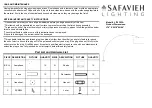
Connection between the light and DMX/RDM console with DMX connector cable as below:
NC
NC
NC
NC
GND 1
DATA- 2
DATA+ 3
②
DMX Terminator
ln DMX control mode, the DMX output of the last fixture should be connected with a DMX terminator
(Not included). This prevents interference caused by DMX signals in the transmitting process. The terminator
is connected with a 120Ω(OHM) resistor across Pin 2 and Pin 3. (As shown below)
DMX Terminator Connection
Connect a 120Ω resistor across
Pin 2 and Pin 3 in an XLR plug
and insert into the DMX OUT
socket on the last unit.
PIN 2
P IN 3
120Ω
1
2
3
5
4
DMX IN
1 GND
2 DATA-
3 DATA+
DMX OUT