background image

14

5.   INSTALLATION AND ASSEMBLY

WARNING

5-3 Installation and assembly

5-3-1 Adjusting the level adjusters

z

z

z

z

z

Regarding the adjustment of the level adjusters of the machine, refer to the separate
CABINET Operation Manual.

5-3-2 Connecting the power cord and ground lead

z

z

z

z

z

Regarding the connection of the power cord and ground lead, refer to the separate
CABINET Operation Manual.

5-3-3 Inserting the USB key - To be conducted by a technician only -

z

z

z

z

z

To protect the service staff and other people from an electric shock, accident and
injury, and to prevent damage to the electrical circuitry of the machine, always turn
off the power switches before initiating the described task.

z

z

z

z

z

The USB key provided with the product is designed exclusively for this
game machine. Never use it in any other machine. Also, do not insert any
other USB key into this machine. Failure to observe this instruction can
result in equipment malfunctions.

z

z

z

z

z

Make  sure  that  the  power  switch  of  the  machine  is  turned  off  before
inserting the USB key.

z

z

z

z

z

Be sure to install one USB key to each Game PC Board.

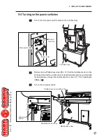
Turn off the main power switch of the machine.
(See P. 17 “5-4 Turning on the power switches of the cabinet”  .)
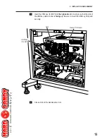
Remove the one Phillips truss screw (M4 x 10). Using the provided maintenance
key, open and dismount the maintenance door.

Phillips truss screw 
(M4 x 10)

Maintenance key

Maintenance door

Содержание TEKKEN 6 BLOODLINE REBELLION SD-S

Страница 1: ...a safe place for quick access whenever needed WARNING The actual product may differ slightly from the illustrations in this manual TEKKEN 6 BLOODLINE REBELLION SD S Part No 722 570 First Edition Publi...

Страница 2: ...tain and discard the Game PC Board z How to operate the CabinetAssy installed with the Game PC Board correctly and make full use of its features CABINET Operation Manual z Information for proper use o...

Страница 3: ...ous injury CAUTION Failure to avoid the indicated risk may result in minor injury or property damage Notes related to machine functions but not to safety are marked with the following label Notes rela...

Страница 4: ...z Do not wet the power cord or power cord plug with water Water can cause an electric shock or leakage z z z z z Do not touch the power cord with a wet hand Doing so can result in an electric shock z...

Страница 5: ...th ample illumination and keep the labels clean at all times Also make sure that the labels are not hidden behind another game machine or other objects i i i i i Do not remove or alter the warning lab...

Страница 6: ...12 5 2 Required dimensions of carry in passage such as doors and corridors 13 5 3 Installation and assembly 14 5 3 1 Adjusting the level adjusters 14 5 3 2 Connecting the power cord and ground lead 14...

Страница 7: ...NTENANCE 45 8 1 Maintenance and inspection 45 8 1 1 Inspection items 45 1 Inspection of level adjusters 45 2 Inspection of the power cord plug 45 3 Inspection of screws for looseness 45 8 2 Troublesho...

Страница 8: ...6 CONTENTS...

Страница 9: ...0VAC power supply Cabinet P2 Assy 223W 110 120VAC power supply 227W 220 240VAC power supply 3 Maximum current consumption Cabinet P1 Assy 4 3A 110 120VAC power supply 2 2A 220 240VAC power supply Cabi...

Страница 10: ...TS The product package contains the following parts z z z z z Make sure all the parts shown below are contained in the product package z z z z z If parts are missing contact your distributor Product p...

Страница 11: ...ABINET Operation Manual 1 3 Torx wrench 4 mm across flats for M5 1 4 Dummy card EXP 1 5 Vendor POP EXP 1 6 Poster B 1 7 Poster C 1 8 Fighting technique panel A EXP 2 9 Fighting technique panel B EXP 2...

Страница 12: ...uction of the cabinet refer to the separate CABINET Operation Manual This following shows a cabinet for the TEKKEN 6 BLOODLINE REBELLION SD S game Game PC Board STD Connector PC Board Signboard sheet...

Страница 13: ...floor by using the level adjusters Unstable machine installation can result in an accident or injury see P 23 5 3 Adjusting the level adjusters in the separate CABINET Operation Manual 5 1 Installatio...

Страница 14: ...machine z z z z z Set a play zone as shown below so that players can move away from the machine without bumping into observers or passersby z z z z z Regarding the establishment of the play zone duri...

Страница 15: ...d to the installation site The dimensions of the product in the ship ping condition are as follows 820 W x 800 D x 1 700 H mm Weight 140 kg By referring to the dimensions indicated above make sure in...

Страница 16: ...cuitry of the machine always turn off the power switches before initiating the described task z z z z z The USB key provided with the product is designed exclusively for this game machine Never use it...

Страница 17: ...t the USB key for EXP into the right side slot making sure that the side of the USB key with a sticker is facing up Be sure to insert the USB key firmly and securely USB key for EXP Game PC Board Slot...

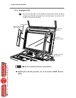
Страница 18: ...attach them to the flat sections on both sides of the monitor on the front of the machine z z z z z Be sure to attach the POP in the correct direction z z z z z Regarding other assembly procedures re...

Страница 19: ...maintenance door on the front side of the machine unlock the lock using the maintenance key provided with the Cabinet Assy and open the maintenance door See P 14 5 3 3 Inserting the USB key Turn on t...

Страница 20: ...ed vendor POP EXP to the card vending machine and set the dummy cards P EXP Card vending machine The card vending machine is not provided with this product Purchase the speci fied card vending machine...

Страница 21: ...19 6 MOVING AND TRANSPORTING z z z z z Regarding the relocation and transportation of the machine refer to the separate CABINET Operation Manual...

Страница 22: ...or malfunction may result z z z z z The warning labels describe important precautions Observe the following Regarding the label attachment locations see P 3 1 4 Description of warning labels attached...

Страница 23: ...ower cord routed properly so that players and other people will not trip over the cable Check the following items after turning on the power switches If any abnormality is found turn off the power swi...

Страница 24: ...usness If this happens advise the player to consult a doctor as soon as possible Whenpre schoolchildrenplaythegame requesttheirparentsorguardianstoobserve the children Explanation of the game system T...

Страница 25: ...maintenance door unlock the door using the maintenance key supplied with the Cabinet Assy and dismount the maintenance door See P 14 5 3 3 In serting the USB key Turn on the sub power switch and reins...

Страница 26: ...ervice switch red Press this switch to increase the credit count without activating the coin counter b Test switch red Press this switch in the game mode to enter the test mode c Sound volume Use this...

Страница 27: ...en MENU 2008 12 03 WED 10 15 30 LOADED SOFTWARE SERIAL NUMBER 000000 00000 SOFTWARE UPDATE DISPLAY TEST SOUND TEST JVS STATUS INPUT TEST CARD RW TEST GAME OPTIONS COIN OPTIONS CLOCK SETTING CLOSE TIME...

Страница 28: ...test mode After making adjustments return to the test mode menu screen Select EXIT SAVE and press the P1 Button switch 1 The test mode ends and the display returns to the Attract screen z z z z z Be s...

Страница 29: ...the image display size display position aspect ratio and distortion Each time the P1 Button switch 1 is pressed the screen indication changes alter nately between the above mentioned two screens Selec...

Страница 30: ...he P1 Button switch is pressed a test sound is produced from the left speaker first followed by the right speaker and then by both speakers The sound level can be adjusted by using the sound volume lo...

Страница 31: ...RATION To return to the test mode menu screen press the P1 Start switch To exit from the test mode follow the procedure described in 7 4 2 Exiting from the test mode on page 26 P1 Start switch P1 side...

Страница 32: ...elect JVS STATUS on the test mode menu screen see page 25 and press the P1 Button switch 1 The JVS Status screen appears To return to the test mode menu press the P1 Start switch To exit from the test...

Страница 33: ...do not change according to the lever button operations the game cannot be played properly If this happens refer to 8 2 Troubleshooting on page 46 To return to the test mode menu screen press the P1 Bu...

Страница 34: ...screen 1 Up to two stacked cards can be inserted The above screen appears when two cards are inserted in the card reader writer unit on the P1 side If a card not supported by the machine is inserted...

Страница 35: ...appears when W R TEST is executed for the card reader writer unit on the P2 side When the test ends successfully W R TEST OK is indicated on the right side of the CARD 1 indication If W R TESTING is...

Страница 36: ...serted card from the card reader writer unit P1 8 direction lever P1 Button switch 1 P2 8 direction lever P2 Button switch 1 P1 side P2 side P1 Start switch P1 side P2 side To return to the test mode...

Страница 37: ...8 direction lever to right or left to change the setting The default setting is indicated in green Game Options screen A B C D E F G H I J K L M N GAME OPTIONS DEFAULTS IN GREEN DIFFICULTY LEVEL MEDIU...

Страница 38: ...one round Change of game character for continuity game Change of game character when another player barges in 1 Sound in Attract mode ON Game over for both players when tournament mode game ends Colo...

Страница 39: ...o select an item and change its setting Move the P1 8 direction lever up or down to select an item and move the P1 8 direction lever to right or left to change the setting The default setting is indic...

Страница 40: ...added by one operation of Coin switch 1 Free play setting Item Options Default Remarks setting A START COST B COUNTINUE COST C COIN CHUTE1 MECHANICAL VALUE D FREE PLAY 1 2 3 4 5 6 7 8 9 1 2 3 4 5 6 7...

Страница 41: ...ver to right or left to change the setting The day of the week indication is automatically set when the Year Month and Day are changed To return to the test mode menu screen press the P1 Start switch...

Страница 42: ...s Operate the lever on the control panel to select an item Move the P1 8 direction lever up or down to select an item and move the P1 8 direction lever to right or left to change the setting The defau...

Страница 43: ...ting A SCHEDULE TYPE B HOURS C MINUTES DAY WEEK 24 25 26 ALL 19 20 21 22 23 24 00 15 30 45 00 DAY 24 00 Close Time Setting setting chart To return to the test mode menu screen press the P1 Start switc...

Страница 44: ...data Select BOOKKEEPING on the test mode menu screen see page 25 and press the P1 Button switch 1 The Bookkeeping screen appears To return to the test mode menu screen press the P1 Start switch To exi...

Страница 45: ...SH ROM DATA CLEAR SET DEFAULTS ALL OPTIONS ALL CLEAR SELECT P1 UP DOWN ENTER P1 BUTTON1 EXIT P1 START FLASH ROM FORMAT G P1 8 direction lever P1 Button switch 1 P1 side P2 side A CANCEL Cancels the cu...

Страница 46: ...RATION To return to the test mode menu screen press the P1 Start switch P1 Start switch P1 side P2 side To exit from the test mode follow the procedure described in 7 4 2 Exiting from the test mode on...

Страница 47: ...owing regularly 1 Inspection of level adjusters 1 Make sure that the machine is stably installed See 5 3 Adjusting the level adjusters on page 23 of the Cabinet Operation Manual 2 Inspection of power...

Страница 48: ...ding parts for repair pack them carefully When sending the Game PC Board wrap them in sponge or bubble wrap and place them in a corrugated cardboard box to protect against external impact Be sure to a...

Страница 49: ...USB key is for Tekken 6 Initialization of the USB key failed at startup Flash ROM formatting for the USB key failed USB memory stick was connected together with the USB key when the machine started Re...

Страница 50: ...ry of the machine always turn off the power switches before initiating the described task Turn off the power switches of the machine See P 17 5 4 Turning on the power switches of the cabinet Remove th...

Страница 51: ...erse z z z z z Be sure to insert the removed USB key into the new Game PC Board Without the USB key the game machine does not function properly See P 14 5 3 5 Inserting the USB key z z z z z When tran...

Страница 52: ...ss z z z z z To protect the service staff and other people from an electric shock accident and injury and to prevent damage to the electrical circuitry of the machine always turn off the power switche...

Страница 53: ...head screws with flat and spring washers No 6 UNC x 4 16 dismount the HDD for EXP from the HDD bracket and replace the HDD Reinstall the parts by following the removal sequence in reverse Phillips pa...

Страница 54: ...hine the machine must be collected transported and discarded in accordance with the local laws and regulations z z z z z When entrusting a third party to collect transport and discard the machine be s...

Страница 55: ...53 9 DISCARDING THE MACHINE...

Страница 56: ...ype and rating Parts No 1 Dummy card EXP 1 722 567 2 Vendor POP EXP 1 722 568 3 TEKKEN 6 BLOODLINE REBELLION 1 This manual 722 570 SD S Operation Manual 4 CABINET Operation Manual 1 719 705 10 PARTS L...

Страница 57: ...2 Instruction sheet EXP 1 722 585 3 P1 sticker 1 719 717 4 P2 sticker 1 719 718 5 Fighting technique panel A EXP 1 722 565 6 Fighting technique panel B EXP 1 722 566 7 STD Connector PC Board 1 306 952...

Страница 58: ...56 10 PARTS LIST...

Страница 59: ...Blk Wht Blu Wht Red Yw Brn Yw Yw Blk Blk Red Red Blk Blk Org 1 core shielded cable x 2 Noise filter Inlet 3P GND Cord box Circuit protector Note 2 Cord box Assy sub power switch MATE N Note 1 MATE N...

Отзывы: