


8
Installation and operation manual
–
DTHC-V4-2020
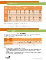
Dim
UNIT DIMENSIONS
39
45
56
62
73
84
95
112
140
169
Imperial [in]
A
57
63
3/4
68
7/8
74
1/4
B
55
3/8
63
3/8
63
1/2
80
1/4
C
64
3/4
70
3/4
76
1/4
95
3/4
D
6
3/4
6
3/4
6
3/4
6
3/4
L
6
6
8
8
M
27
7/8
31
3/4
31
3/4
40
3/4
N
8
1/2
8
1/2
9
1/2
9
1/8
P
16
3/8
18
7/8
16
7/8
23
1/4
Q
23
26
30
35
R
48
1/2
54
1/2
60
75
1/2
T
21
1/2
21
1/2
21
1/2
22
1/2
26
U
14
1/2
17
23
28
V
20
5/8
23
3/8
20
3/8
26
3/4
W
29
5/8
35
36
3/4
37
3/4
39
1/4
46
1/4
AA
72
7/8
82
5/8
90
1/4
100
7/8
F
25
28
32
37
E
9
1/4
9
3/8
9
3/8
9
5/8
S
45
51
56
1/2
72
NN
24
1/4
27
1/4
30
7/8
35
5/8
Dim
Metric [mm]
A
1448
1619
1749
1886
B
1407
1610
1613
2038
C
1645
1797
1937
2432
D
171
171
171
171
L
152
152
203
203
M
708
806
806
1035
N
216
216
241
232
P
416
479
429
591
Q
584
660
762
889
R
1232
1384
1524
1918
T
546
546
546
572
660
U
368
432
584
711
V
524
594
518
679
W
752
889
993
959
997
1175
AA
1851
2099
2292
2562
F
635
711
813
940
E
235
238
238
244
S
1143
1295
1435
1829
NN
616
692
784
905


