


9
Installation and operation manual
–
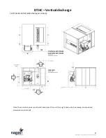
DTHC-V4-2020
•
Install the unit on the positive side of the air-circulating blower (supply side).
•
The air intake must be located in order to avoid snow, rain, flammable, toxic gases and other
harmful substances from entering the heater.
•
In operation mode, the system design must provide enough air to the heat exchanger to ensure a
temperature rise between 50°F (28°C) and 120°F (67°C) and maintain an average supply
temperature of 130°F (54°C) maximum. Note that the temperature high limit protection is
factory set at 160°F (71°C).
•
The inlet ducting must have the same cross-sectional area as the inlet connection. Both inlet and
outlet ducts must have a removable access panels. These panels shall be sized to permit
inspection of the heat exchanger at start-up on routine inspection.
•
If fire dampers are used, they must be equipped with switches connected to the safety control
circuit in order to interrupt the heater if there is a fire or high temperature in the ventilation
duct. The electric actuators must be adjusted in order to close the safety loop on the flame
safeguard only when the dampers are fully open.
•
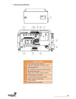
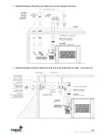
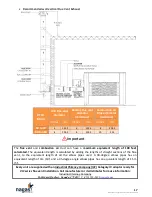
Depending on the model, the flue vent connection diameter ranges from 6 to 8 inch. The DTHC
models are designed to operate effectively and safely with a
positive stack (category IV) type
sealed single wall or double wall corrosion resistant flue vent listed for this application, whether
vertical or horizontal arrangement or a combination of both. The minimum diameter of all
sections must be identical to the unit’s connection diameter. Refer to the exhaust system
sections of this manual.
•
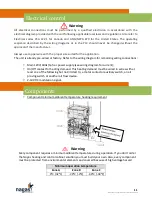
If no control cabinet is supplied by
Nagas
with the unit the installer must be made one for
component protection and must include aeration openings at least equal of two 2 inches holes.
See gas installations code for more requirements.
IMPORTANT NOTICE
•
In order to minimize the risk of freezing pipes inside the building, the installer must equip
the system with a low temperature sensor that will interrupt operation, stop the fan and
close the dampers in the event that low temperature (lower than 40
o
F) are detected
downstream of the heater.
•
This unit will produce condensate in variable quantity depending of many conditions. This
corrosive liquid must be treated and drain correctly with provision to prevent freezing. See
Drain line installation
sections for details.
•
It is necessary to mechanically attach the unit to the roof base or other support structure
with screws or other suitable fasteners to prevent wind or earthquake damage.
Installation guidelines


