DF Series installation manual
26
www.nagasinnovation.com
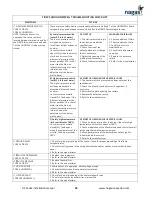
MAXITROL TROUBLESHOOTING CHECK LIST
SYMPTOMS
POSSIBLE CAUSE
ON-SITE CHECK
ACTIONS
NO GAS FLOW
1. Modulating valve Improperly
installed or defective
1. The arrow on the side of the
valve must point in the direction
of the gas flow.
1. Install the valve properly.
CONTINUOUS LOW FIRE
(ELECTRONIC PROBLEM)
2. No voltage to the amplifier.
3. Open circuit in TD114
(circuit or wiring)
4. Short circuit in TS114,
(circuit or wiring)
5. Defective amplifier
2. Check for 24 VAC supply at
amplifier terminals 7 and 8.
3. Check for loose or broken wires
between amplifier terminals 1
and 2 and between TD114
terminals 1 and 3.
4. Connect the test resistor
between terminals 3 and 4 of the
amplifier and disconnect the
wiring. Follow Maxitrol analysis
procedure.
5. Perform checks 2, 3 and 4.
2. Verify the power source.
3. Tighten connections or replace
wiring.
4. If a modulating signal is read,
check TS114 for short circuits.
Replace the TS114 if necessary.
5. If steps 2, 3 and 4 do not solve
the problem and a modulating
signal is still not read, replace the
amplifier.
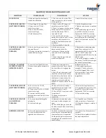
CONTINUOUS LOW FIRE
(NO ELECTRONIC
PROBLEM)
6. Short circuit or open circuit in
the amplifier coil
7. Missing, jammed or improperly
installed valve plunger.
6. With control wires
disconnected, check the
resistance at the connecting
terminals of the modulating
valve.
7. Check the plunger; it should
move freely upward.
6. Replace the modulating valve
head if the resistance is not
approximately 45-55 ohms for the
M511 or ES371 valves and
approximately 60-80 ohms for the
MR212 valve.
7. Clean the plunger or replace it
if necessary. Install it according to
the instructions provided.
LOW FIRE - PULSATING
OR ERRATIC FLAME OR
IMPROPER CAPACITY
8. Incorrect low fire adjustment.
9. Excessive negative pressure at
burner
8. Make sure that low fire is
properly adjusted. There should
be a low flame throughout the
burner.
9. Shut off main gas supply and
check the suction at the elbow
located before the burner while
the blower is in operation; the
negative pressure should not
exceed 1.5 inches of water for the
M511.
8. Adjust the low fire.
9. If the negative pressure
exceeds 1.5 inches of water,
check for clogged filters or air
inlet restrictions. Refer to the
manufacturer for other
suggestions.
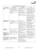
CONTINUOUS HIGH FIRE
(ELECTRONIC PROBLEM)
10. Short circuit in TD114
(circuit or wiring)
11. Open circuit in TS114/TS1007
(circuit or wiring).
12. Jumper not connected
between terminals 2 and 3 of the
amplifier.
10. Check for short circuits at
amplifier terminals 1 and 2 and
TD114 terminals 1 and 3.
11. Check TS114 for open circuits.
Follow step 4.
12. Make sure jumper is
connected.
10. Correct wiring if necessary.
11. If a modulating signal is read,
check TS114 for open circuits.
Replace the TS114 if necessary.
12. Correct the wiring.
CONTINUOUS HIGH FIRE
(NO ELECTRONIC
PROBLEM)
13. Foreign object holding the
valve open.
14. Jammed plunger.
13. Remove valve bottom plate
and inspect valve plunger and
seat.
14. Check the plunger; it should
be clean, smooth and move freely
in the valve.
13. Clean the seat. Clean the
valve or replace it if necessary.
14. Clean the plunger or replace if
necessary.
ABNORMAL HIGH FIRE
15. Gas inlet pressure too low.
16. Incorrect adjustment of
regulator outlet pressure.
15. Make sure that the minimum
inlet pressure recommended by
the manufacturer is respected.
16. Adjust the gas inlet pressure
according to the manufacturer’s
specifications.
15. Increase the inlet pressure if
possible.
16. Adjust the regulator to obtain
the required pressure.


