background image


DF Series installation manual  

20


www.nagasinnovation.com 

9.


OPERATING SEQUENCE FOR SINGLE VOLUME DIRECT FIRED HEATER 

(For guidance only) 


Starting up the burner 

a.


Create a heating demand. 

b.


If outside temperature is under 70°F, the outside temperature sensor (TDA) 
allows for the FIREYE flame safeguard to be energized. 

c.


Authorization for pilot to ignite is complete when the low and high air pressure 
differential and high temperature limit switches are closed. 

d.


The burner starts. 

e.


The MAXITROL controller modulates the burner to maintain the selected set 
point of the temperature selector. 


10.


OPERATING SEQUENCE FOR DOUBLE VOLUME DIRECT FIRED HEATER 

(For guidance only) 


Starting up the burner 

a.


Create a heating demand. 

b.


If outside temperature is under 70°F, the outside temperature sensor (TDA) 
allows for the FIREYE flame safeguard to be energized. 

c.


The burner starts. 

d.


In low volume mode, when airflow is reduced either by the inlet damper or by 
a VFD, the profile plate damper opens partially and modulates to maintain the 
required air pressure drop across the burner. 

e.


In high volume mode, when airflow is increased either by the inlet damper or 
by a VFD, the profile plate damper opens wider and modulates its position to 
maintain the required air pressure drop across the burner. 

Содержание DF 100

Страница 1: ...DIRECT GAS FIRED AIR HEATER DF SERIES INSTALLATION AND OPERATION MANUAL CUSTOM GAS SOLUTIONS LEGENDARY PERFORMANCE ...

Страница 2: ...ly read the installation start up and maintenance instructions before installing or servicing this unit GAS ODOR If a gas odor is detected 1 Open all windows 2 Do not touch any switches 3 Extinguish all open flames 4 Immediately notify your gas supplier WARNING Using or storing fuel or any other flammable liquid or gas in open containers near this unit is dangerous ...

Страница 3: ...ON 6 2 GAS CONTROL PANEL INSTALLATION 7 3 GAS PIPING CONNECTIONS 8 4 ELECTRICAL CONTROL SENSORS CONNECTIONS 9 5 AIR PRESSURE SWITCH CONNECTION 10 6 IGNITION AND FLAME DETECTIONS CONNECTIONS 10 7 START UP INSTRUCTIONS 12 8 HEATER SHUTDOWN 19 9 OPERATING SEQUENCE FOR SINGLE VOLUME DIRECT FIRED HEATER 20 10 OPERATING SEQUENCE FOR DOUBLE VOLUME DIRECT FIRED HEATER 20 11 TROUBLESHOOTING 21 START UP REP...

Страница 4: ...NFPA 70 in the USA and all local applicable codes for this category of equipment All electrical installations must comply with the electric diagrams of the heater For more information refer to the start up instructions operating and adjustments instructions and wiring diagram supplied with the unit WARNING This air heater must ALWAYS Be used to heat outside air 100 fresh air No recirculation air i...

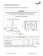
Страница 5: ...e plate installation 2 Control panel installation 3 Gas piping connections main burner pilot and vents 4 Electrical control sensors connections 5 Differential pressure switches connections 6 Ignition wire and flame detection rod connections or ultra violet detector connections 7 Start up instructions DF HEATERS TYPICAL ASSEMBLY Consult the manufacturer for any other assembly arrangement Profile pl...

Страница 6: ...ng to allow the insertion of the profile plate at the chosen location CLEARANCES TO BE RESPECTED Table of clearances Model F G H in mm in mm in mm DF 25 50 75 100 1 25 6 152 30 762 DF 150 12 305 DF 200 300 375 40 1016 DF 450 550 700 18 457 50 1270 if water coils or flat filters are installed upstream this dimension has to be increased if a plenum fan is used this dimension has to be increased by 5...

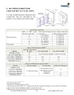
Страница 7: ...dth of the control panel length TYPICAL PIPING SCHEMATIC OF AN INSTALLATION WITH THE PANEL MOUNTED DIRECTLY ON UNIT TYPICAL PIPING SCHEMATIC OF AN INSTALLATION WITH THE PANEL REMOTELY MOUNTED FROM UNIT NOTE It is possible to install the control panel remotely from the profile plate Standard wires and tubes length provided with the heater is six feet two meters For installation requiring a longer d...

Страница 8: ...BH and less Use external gas regulator to reduce to psig From 751 to 1000 MBH 1 From 1001 to 2500 MBH 1 1 1 From 2501 to 5000 MBH 2 1 2 5001 MBH and more 3 2 3 Pilot vent and bleed valve pipe size NPT 1 2 Capacity Pilot line diameter Vent diameter Bleed valve4 750 MBH and less IRI option aluminum tubing Not required 2 x 2 Ø openings are required in cabinet for ventilation From 751 to 1000 MBH From...

Страница 9: ...e of operation of the electrical diagram must never be modified without consulting the manufacturer Electrical controls location Installed by others Items Description All wires must comply with codes and in their absence National Electrical Code NFPA70 1 Low temperature limit sensor Freeze stat optional BL 2 Modulation sensor MT1 12 TS114 Shielded wires required 3 High limit air temperature contro...

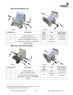
Страница 10: ...propriate hardware to pass the tubes through unit wall 6 IGNITION AND FLAME DETECTIONS CONNECTIONS SNAPPING BUSHING IF DOUBLE WALL RUBBER GROMMET BLACK PLASTIC TUBE PROFILE PLATE PROFILE PLATE SUPPORT PROFILE PLATE SUPPORT RUBBER GROMMET PLASTIC TUBE BLACK RING ALUMINUM TUBE 1 8 PIPE 1 4 TUBE ADAPTOR SNAPPING BUSHING IF DOUBLE WALL ALUMINUM TUBE IN UNIT BLACK TUBE CLEAR TUBE IN CONTROL BOX ...

Страница 11: ...BH GTO 15 Red with blue stripe 13mm 4 Pilot gas tubing With ultra violet flame detector Components Description Wire gauge Color Hole diameter to drill in wall5 1 Pilot ignition wire GTO 15 Black 13mm 2 Pilot ultraviolet detector 166 Supplied by others 22mm 3 Burner ultra violet detector two required for a capacity 2500 MBH 22mm 4 Pilot 5 Use rubber grommets where wires pass through sheet metal wal...

Страница 12: ...rmation should only be used by a qualified technician for gas equipment installation with qualification cards with knowledge in electricity and ventilation WARNING Smoking is not recommended during the heater start up Voltmeter Ammeter Temperature reading device Tachometer for blower RPM Air pressure gauge 0 to 2 w c scale Gas pressure gauge 2 to 20 w c scale Recommended tools ...

Страница 13: ...1 Pa DF 150 200 300 375 450 550 700 Min 13 w c 3235 Pa Min 11 w c 2734 Pa Max 14 w c 3484 Pa Max 14 w c 3484 Pa For lower gas pressure consult manufacturer b Ensure that the air is completely purged from the gas piping c The inlet gas pressure difference from the burner operating at high fire and the burner OFF should not exceed 1 inch of water column 249 Pa WARNING WHILE THE BURNER IS IN OPERATIO...

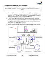
Страница 14: ...er profile plate is too high or too low the unit will not function properly This could produce an excess of carbon monoxide CO or trigger a FLAME FAILURE alarm b To measure the differential pressure at the burner profile plate the blower must be in operation and discharge air temperature maintained at 70 F 21 C In winter to maintain this temperature the burner must be in operation and the temperat...

Страница 15: ...d to the value indicated in the graph below 40 35 30 25 20 15 10 5 0 5 10 15 20 25 30 35 40 45 50 55 60 65 70 75 80 85 90 95 0 4 0 5 0 6 0 7 0 8 40 36 32 28 24 20 16 12 8 4 0 4 8 12 16 20 24 28 32 36 40 100 110 120 130 140 150 160 170 180 190 200 Outside air temperature F Static pressure drop inches w c Outside air temperature C Static pressure drop Pa ...

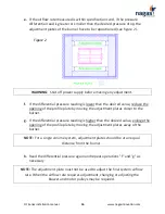
Страница 16: ...ning of the profile plate by moving the adjustment plates closer to the burner g If the differential pressure reading is higher than the desired value enlarge the opening of the profile plate by moving the adjustment plates away of the burner NOTE For a single volume system adjustment plates should be at an equal distance from the burner h Read the differential pressure again and repeat operations...

Страница 17: ...mperature 20 F 29 C Desired final temperature 70 F 21 C Temperature rise ΔT 90 F 50 C b When the outside temperature does not allow for the simulation of the specified temperature rise across the burner adjust its maximum capacity according to the required gas pressure indicated on the name plate of the unit Readjustment will be required when outside air temperature permits full fire c The adjustm...

Страница 18: ...outside air temperature permits full fire M511 M611 or ES371 MR212 FINAL AIR TEMPERATURE ADJUSTMENT a Set the MAXITROL temperature selector TD 114 to the desired final temperature This selector is located either in the control panel on the unit or in the remote control station NOTE When the MAXITROL temperature selector TD 114 is installed in a remote control station the wires used to make the con...

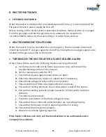
Страница 19: ...he following checks must be performed a Verify the alarm code on the flame supervision relay and consult the troubleshooting section of this manual b Set the main power switch to OFF c Ensure that all gas supply manual valves are open d Check the blower belts replace or adjust them if necessary e Check flame safeguard relay and fire rod condition f Check condition of filters and replace them if ne...

Страница 20: ...he selected set point of the temperature selector 10 OPERATING SEQUENCE FOR DOUBLE VOLUME DIRECT FIRED HEATER For guidance only Starting up the burner a Create a heating demand b If outside temperature is under 70 F the outside temperature sensor TDA allows for the FIREYE flame safeguard to be energized c The burner starts d In low volume mode when airflow is reduced either by the inlet damper or ...

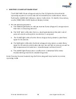
Страница 21: ...mit switches are closed and terminal 6 is energized c The PTFI light is ON only during the pilot ignition cycle d The FLAME light is ON only when the flame safeguard relay detects a flame signal and is not in alarm mode e The ALARM light flashes when a malfunction is detected f The last 6 alarm codes are stored in the relay s memory A plug in display is required to read them Notes a When an alarm ...

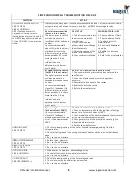
Страница 22: ...on and operation manual of the flame relay manufacturer for any code not listed in this table CONSULT THE FIREYE TROUBLESHOOTING TABLE TO ESTABLISH THE DIAGNOSTIC Trouble code Trouble description alarm OPR CTRL AIRFLOW PTFI FLAME ALARM 6 Frequency noise 7 Flame failure PTFI 19 Flame failure MTFI 21 Open air pressure switch 54 Ground fault 55 Faulty programmer 56 Faulty amplifier Light ON OFF Flash...

Страница 23: ...ing demand b The PILOT light is ON when there is a heating demand and the pilot control valve coil as well as the ignition transformer is energized c The FLAME light is ON when the flame safeguard relay detects a pilot flame signal for 10 seconds d The MAIN light is ON when the flame safeguard relay detects a stable flame signal for 10 seconds and all safety devices low and high air pressure as we...

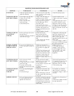
Страница 24: ...nel it should be set to BURNER 3 Check the outside temperature thermostat it prevents the burner from running if the outside temperature is over 70 F 4 Check the burner purge time delay relay 5 Refer to the manufacturer FREQUENCY NOISE CODE 6 FIREYE 1 Check if a high voltage source is located near the flame safeguard relay 2 Check electrical wiring from the building junction box to the heater 3 Re...

Страница 25: ... N C and open if the differential pressure at the burner exceeds 1 2 inches of water see the Start up Instructions section for more information on the adjustment of the burner profile plate AT START UP OR WHEN THE HEATER IS IN USE 1 The duct work static pressure drop does not meet the specifications 2 Check size of pulleys and adjust or change them if necessary 3 Adjust profile plate opening if ne...

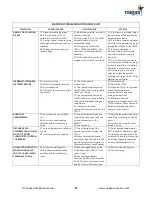
Страница 26: ...s provided LOW FIRE PULSATING OR ERRATIC FLAME OR IMPROPER CAPACITY 8 Incorrect low fire adjustment 9 Excessive negative pressure at burner 8 Make sure that low fire is properly adjusted There should be a low flame throughout the burner 9 Shut off main gas supply and check the suction at the elbow located before the burner while the blower is in operation the negative pressure should not exceed 1 ...

Страница 27: ...correspond to the desired average discharge air temperature 24 Disconnect the room thermostat from terminal 2 of the TD114 21 Correct wiring 22 Adjust the TD114 23 Move the TS114 to a location where the temperature corresponds to the desired average temperature 24 Make sure that the temperature corresponds to the TD114 set point Check the room thermostat setting and check wiring for short circuits...

Страница 28: ...uct thermostat ______ºF Pre purge delay ______sec Start up delay on low fire ______sec Inlet temperature thermostat ______sec Profile plate openings _______ X _______ _______ X _______ Main fixed Auxiliary motorized Start up completed If no why or others ____________________________________________________________________________________________________ ____________________________________________...

Отзывы: