16 of 26
GT 710-8710 OPUS Low Energy Swing Doors Quick Set-Up and Parts Guide
www.NabcoEntrances.com
P/N C-00178
Rev 12-20-17
DN 1375
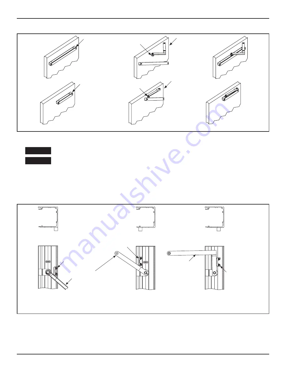
21” Track
Inswing Arm
Wheeled Roller
Wheeled Roller
Inswing Arm
“0” Reveal
12-1/4” Track
Figure 24
Insert the Swing Arm into the Track
CHAPTER 8: INSTALL THE ARM STOP
Power must be turned OFF while installing the Arm Stop.
Do Not drill screw holes for the Arm Stop into the Motor/Operator!!!
1. Turn Power OFF.
2. Manually open the Swing Door 90 degrees or Full Open position.
3. Position the Arm Stop at the bottom of Header according to type of Swing Arm and Reveal.
4. Use the Arm Stop as a template to mark and drill (2) 7/32 inch diameter screw holes.
5. Secure the Arm Stop with (2) 1/4-20 x 1 inch Self Tapping screws.
DN 1064
INSWING ARM
0 1/4” REVEAL
INSWING ARM
GREATER THAN
1/4” REVEAL
OUTSWING ARM
Outswing
8400
8500
8600
8710
Inswing
8400
8500
8600
8710
Inswing
8400
8500
8600
8710
***CAUTION***
Remove Operator
before drilling holes
for Arm Stop
***CAUTION***
Remove Operator
before drilling holes
for Arm Stop
***CAUTION***
Remove Operator
before drilling holes
for Arm Stop
Posi on Arm Stop as shown.
Drill (2) 7/32” diameter holes.
Fasten with (2) 1/4-20x1-1/2” screws.
Posi on of Swing Arm
when Swing door is
opened to desired posi on.
Posi on Arm Stop as shown.
Drill (2) 7/32” diameter holes.
Fasten with (2) 1/4-20x1-1/2” screws.
Posi on Arm Stop as shown.
Drill (2) 7/32” diameter holes.
Fasten with (2) 1/4-20x1-1/2” screws.
Posi on of Swing Arm
when Swing door is
opened to desired posi on.
Figure 25
Arm Stop Configurations
CAUTION
CAUTION


