


Rev. 7-29-15
Part #15-9324
www.NabcoEntrances.com
1400 Folding Door System w/Opus Control
Install the Door Panel
6-22
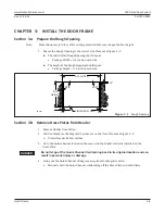
Figure
4-3
Install Bottom Pivot Door Portion Assembly into Web
DN 0330
1/4” Star Washer
Spacer for Bo om Pivot
Web
1/4-20 x 1/4” Hex Screw
Pivot S le
Bo om Pivot
3.3
Secure Spindle Drive Bar to Folding Door
Note:
The Drive Bar is installed to the Channel Guide at the NABCO Factory for shipping purposes only and
must be removed from the Channel Guide before the Folding Door can be installed.
1. Ensure the Pin or 1/8 inch Allen Wrench is still inserted into the Lovejoy Coupling Access Hole.
2. Go to the Spindle Drive Bar. Remove the Hex Bolt and Nut.
a. Please refer to the Shipping Sticker located on the Spindle Drive Bar.
3. Release the Spindle Drive Bar from the Guide Channel.
a. The Spindle Drive Bar can be pushed up toward the Header or down into the Top Web of
the Folding door, but will remain at a 90 degree angle.
b. The Guide Channel can now freely swing closed or open.
4. Swing the Guide Channel up against the Magnetic Latch.
Figure
4-4
Release Spindle Drive Bar from Guide Channel
DN 0844
Nut
Guide Channel
Spindle Drive Bar
Bolt
Spindle Drive Bar - 90 Out
(Lowered down from Header)
Guide Channel
90
3.4
Secure Folding Door to Frame
1. With the Folding Door still on a lat surface, go to the Pivot End of the Top Web. Remove (4)
1/4-20 x 3/4 inch Hex Head Screws and (4) 1/4 inch Star Washers from Riv-nuts located inside
the Web. Save hardware for reinstallation.
Figure
4-5
Remove Screws and Star Washers
DN 0845
1/4” Star Washer
1/4-20 x 2”
Phillips Head Screw
Web