background image


www.myirtech.com 


MYS-6ULX-IOT |


Product Manual 


17 

4.8 LCD & Touch Panel Interface 

i.MX6ULL processor provides


one parallel display port, support max 85 MHz display clock 

and up to WXGA (1366 x 768) at 60 Hz. A 50 pins FPC connector have been used for the 

display  port  on  the  MYS-6ULX-IOT.Linux  drivers  are  provided  to  work  with  MIYR  LCD 

panels for 4.3 inch LCD(480*272) and 7 inch LCD(800*480).Resistance and capacitance 

touch panel are supported.Please refer to below for detail design of LCD interface. 

If you need more information on the LCD panels,please visit www.myirtech.com. 


Figure 4-8 LCD & Touch Panel Interface 

4.9 USB 

i.MX6ULL processor provides two high speed (HS) USB 2.0 OTG (Up to 480 Mbps), with 

integrated HS USB PHY.OTG1 port is connected to a standard micro USB OTG connector 

(Type AB),which can be used as host and slave. OTG2 is connected to a USB Hub chip 

(USB2422/MJ from Microchip),which is used to expand two USB host controller. The two 

expanded  USB  host  are  connected  to  a  standard  USB  host  connector  (Type  A)  and  a 

Содержание MYS-6ULX-IOT

Страница 1: ...www myirtech com MYS 6ULX IOT Product Manual 1 MYS 6ULX IOT Product Manual Version V1 0 22 Jan 2017 ...

Страница 2: ...www myirtech com MYS 6ULX IOT Product Manual 2 Version History Version Description Date V1 0 Initial version 22 Jan 2017 ...

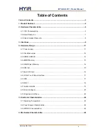
Страница 3: ...esign 11 4 1 Power supply 11 4 2 Clock Resources 12 4 3 DDR3L SDRAM 12 4 4 eMMC Memory 13 4 5 NAND Flash Memory 14 4 6 Ethernet 15 4 7 Micro SD Card 16 4 8 LCD Touch Panel Interface 17 4 9 USB 17 4 10 WIFI 19 4 11 Button LEDs 19 4 12 Boot Configure 20 4 13 Expansion Interface 22 5 Electronic Characteristics 24 5 1 Operating Temperature 24 5 2 Power Supply Characteristics 24 5 3 GPIO DC Characteris...

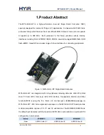
Страница 4: ...ide range of other interfaces for connecting peripherals Figure 1 1 MYS 6ULX IOT Single Board Computer MYS 6ULX IOT are integrated with rich peripherals including Ethernet USB OTG USB Host TF Card WIFI User keys LED LCD interface IO expansion interface and other functions MYIR is using the 14 x 14mm 0 8 mm ball pitch 289MAPBGA package on MYS 6ULX IOT i MX 6ULL application processor on the MYS 6ULX...

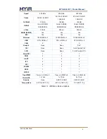
Страница 5: ...net 10 100 Mbit s x 1 10 100 Mbit s x 1 10 100 Mbit s x 2 USB OTG HS FS x 1 OTG HS FS x 2 OTG HS FS x 2 CAN 0 1 2 Graphic None None PxP CSI None None 16 bit Parallel CSI LCD None None 24 bit Parallel LCD Quad SPI 1 1 1 SDIO 2 2 2 UART 4 8 8 I2C 2 4 4 SPI 2 4 4 I2S SAI 1 3 3 ESAI 1 1 1 S PDIF 1 1 1 Timer PWM Timer x 2 PWM x 4 Timer x 4 PWM x 8 Timer x 4 PWM x 8 12 bit ADC 1 x 10 ch 1 x 10 ch 2 x 10...

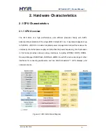
Страница 6: ...at speeds of up to 528 MHz i MX 6ULL includes integrated power management module that reduces the complexity of external power supply and simplifies the power sequencing Each processor in this family provides various memory interfaces including LPDDR2 DDR3 DDR3L Raw and Managed NAND flash NOR flash eMMC Quad SPI and a wide range of other interfaces for connecting peripherals such as WLAN Bluetooth...

Страница 7: ...lude 3x I2S SAI S PDIF Tx Rx 2x 10 100 Ethernet with IEEE 1588 2x 12 bit ADC up to 10 input channel total with resistive touch controller 4 wire 5 wire Partial PMU Integration Security Block TRNG Crypto Engine AES with DPA TDES SHA RSA Secure Boot 14x14 289 MAPBGA 0 8mm pitch 9x9 272 MAPBGA 0 5 mm pitch 2 2 Board Resource MYS 6ULX IOT single board computer is integrated with rich peripherals inclu...

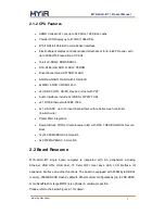
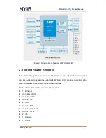
Страница 8: ...d with rich peripherals Extended signal pins are available to expand the peripherals MYS 6ULX IOT provides two 2 0mm pitch 2x20 pin headers to allow users expand other functions Please refer to the below for extend header resource 1 x Ethernet Up to 46 x GPIO Up to 8 x UART Up to 4 x I2C 2 x CAN Up to 4 x SPI Up to 8 x ADC Input Up to 4 x PWM 2 x I2S 1 x Camera 1 x JTAG ...

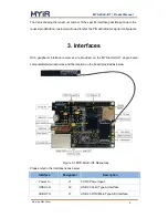
Страница 9: ...al configuration 3 Interfaces Rich peripheral interface resources are provided on the MYS 6ULX IOT single board computer Detailed resources and the location on the board provided as below Figure 3 1 MYS 6ULX IOT Resources Please refer to the interface list as below Interface Designator Description Power In J1 5V DC Power Input USB Host J9 USB2 0 Host Type A Interface USB OTG J7 USB2 0 OTG Micro Ty...

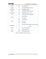
Страница 10: ... Optional Debug UART JP1 Debug UART LVTTL Level LCD J8 24 Bit LCD Touch Panel Interface Buttons S1 System Reset S2 User Button LEDs D14 5V Power LED D12 User LED1 D13 User LED2 Extend Header J2 Expansions for SPI I2C UART Camera and ETH signal J3 TF Card J5 Micro SD Card Socket WIFI U13 USB WIFI Module Switch SW1 Boot Configure Switch Table 3 1 List of MYS 6ULX IOT Resources ...

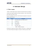
Страница 11: ...it via discrete device Based on the datasheet of i MX 6ULL the CPU power can summarized to 5 power rail which are as below Table 4 1 Item Voltage Power Rail 1 3 3V VDD_HIGH_IN NVCC_xxx VDDA_ADC_3P3 2 1 2V VDD_SOC_IN 3 1 35V NVCC_DRAM 4 3 0V VDD_SNVS_IN 5 5V USB_OTGx_VBUS Table 4 1 I MX6 ULL Power rail MYS 6ULL IOT single board computer is designed to offer power via discrete device circuit instead...

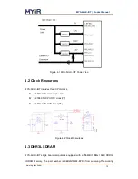
Страница 12: ...S 6ULX IOT includes three CPU clocks 24 Mhz CPU main clock Y1 32 768 Khz CPU RTC clock Y2 24 Mhz USB HUB Clock Y5 Figure 4 2 Clock Resources 4 3 DDR3L SDRAM MYS 6ULX IOT single board computer is equipped with a 256MB 128Mx 16Bit DDR3L SDRAM Memory The part number is K4B2G1646F BYK0 from sumsung The working ...

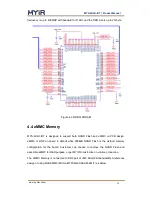
Страница 13: ...both NAND Flash and eMMC on PCB design eMMC is DNP on board in default while 256MB NAND Flash is the default memory configuration for the board Customer can choose to remove the NAND Flash and assemble eMMC for R D purpose or get MYIR to customize on volume production The eMMC Memory is connected to SD2 port of i MX 6ULL 8bit bandwidth A reference design of using 4GB EMMC Micron MTFC4GACAAAM 4M IT...

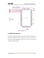
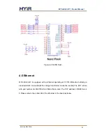
Страница 14: ...emory MYS 6ULX IOT is designed to support both NAND Flash and eMMC on PCB design One NAND Flash with 256MB is connected to the GPMI controller of the processor in default The part number is MT29F2G08ABAEAWP from Micron It can be used to store the system booting code and other information ...

Страница 15: ...quipped with a Ethernet operating at 10 100 Mb s which offering a standard RJ45 connection With voltage transformer inside the socket The PHY silicon with part number of LAN8720A from Microchip is used The PHY address of MIDO bus is 0 Please refer to the schematic of the Ethernet of the board as below ...

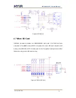
Страница 16: ... processor provides two MMC SD SDIO card ports Port SD2 has been connected to the eMMC and port SD1 is connected to a micro SD card connector 4 bit mode on the MYS 6ULX IOT It can be used to store the system booting code and other information using a mciro SD card memory Figure 4 7 Micro SD Card ...

Страница 17: ...nce touch panel are supported Please refer to below for detail design of LCD interface If you need more information on the LCD panels please visit www myirtech com Figure 4 8 LCD Touch Panel Interface 4 9 USB i MX6ULL processor provides two high speed HS USB 2 0 OTG Up to 480 Mbps with integrated HS USB PHY OTG1 port is connected to a standard micro USB OTG connector Type AB which can be used as h...

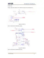
Страница 18: ...Product Manual 18 WIFI module Please refer to the schematic of the USB OTG connector of the board as below Figure 4 9 USB OTG Refer to the schematic of USB Hub as below Figure 4 10 USB Hub Refer to the schematic of USB Host as below ...

Страница 19: ...REALTEK The part number of antenna connector is 1566230 1 from TYCO Customer can choose a proper antenna using the WIFI function according to the part number The USB port of the WIFI module is connected to the USB hub because of the resource constraints of i MX6ULL processor Figure 4 12 WIFI Module 4 11 Button LEDs MYS 6ULX IOT is equipped with a user button Please refer to the schematic of the bu...

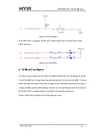
Страница 20: ...e Power On Reset POR where the hardware reset logic forces the ARM core to begin the execution starting from the on chip boot ROM The boot ROM code uses the state of the internal register BOOT_MODE 1 0 as well as the state of various eFUSEs and or GPIO settings to determine the boot flow behavior of the device MYS 6ULX IOT is equipped with a 4 bit switch to change the boot device Please refer to t...

Страница 21: ... NAND Flash version and the eMMC version in the boot Configure Bit1 and Bit2 is used to select boot device Please refer NAND Flash version setting as below Switch BIT1 BIT2 SD Card 0 1 NAND Flash 1 0 Table 4 2 NAND Flash Version Boot Configure Please refer eMMC version setting as below Switch BIT1 BIT2 SD Card 0 0 ...

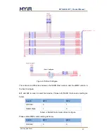
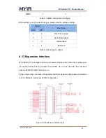
Страница 22: ...nal Boot 1 1 Reserved Table 4 4 Boot Type Configure 4 13 Expansion Interface MYS 6ULX IOT is equipped with two pin header 40 pins with 2 00mm pitch where up to 46 free GPIOs have been provided Those GPIOs also can be used as other functions such as SPI QSPI UART I2C and so on Please refer to the schematic of Expansion Interfaces as below and please be noticed to refer to i MX6ULL data sheet for PI...

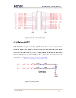
Страница 23: ...n be used as Linux terminal to debug the system A pin header 1x3pins 2 54mm pitch has been used for the debug UART port The debug UART is 3 3V LVTTL Level standard Consumers can use it with a USB to UART TTL level cable MIYR provides suitable cable for selection For more detail please visit http www myirtech com list asp id 537 Figure 4 18 Debug UART ...

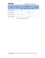
Страница 24: ...r Max Unit Commercial Level 0 70 Table 5 1 Operating Temperate 5 2 Power Supply Characteristics Item Label Parameter Description MIN Normal MAX Unit System Voltage 5V 4 8 5 0 5 5 V Power In System Current Iv5 0 0 26 A Linux system No LCD RTC Voltage VDD_BAT 2 4 3 6 V RTC Power In Table 5 2 Power Supply Characteristics 5 3 GPIO DC Characteristics ...

Страница 25: ... Product Manual 25 Item Label Parameter Description MIN Normal MAX Unit Input High Voltage VIH 2 3 3 3 V Input Low Voltage VIL 0 0 99 V Output high Voltage VOH 3 15 V Output Low Voltage VOL 0 15 V Table 5 3 GPIO DC Characteristics ...

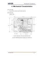
Страница 26: ...uct Manual 26 6 Mechanical Characteristics PCB Layers 8 Layers PCB Immersion Gold Process Lead Free Mechanical 70x55x17 5mm Figure 6 1 Mechanical Information of MYS 6ULX IOT For more details about the board please refer to the DXF file ...

Страница 27: ...well as the matters needing attention in using MYIR s products Service Guarantee MYIR regards the product quality as the life of an enterprise We strictly check and control the core board design the procurement of components production control product testing packaging shipping and other aspects and strive to provide products with best quality to customers We believe that only quality products and...

Страница 28: ...ding service However the following situations are not included in the scope of our free technical support service a Hardware or software problems occurred during customers own development b Problems occurred when customers compile or run the OS which is tailored by themselves c Problems occurred during customers own applications development d Problems occurred during the modification of MYIR s sof...

Страница 29: ...th fingers or hands to leave fingerprint 4 Do not clean the surface of the screen with chemicals 5 Please read through the product user manual before you using MYIR s products 6 For any maintenance service customers should communicate with MYIR to confirm the issue first MYIR s support team will judge the failure to see if the goods need to be returned for repair service we will issue you RMA numb...

Страница 30: ... stopping production we will inform customers in time and assist customers with products updating and upgrading Value added Services 1 MYIR provides services of driver development base on MYIR s products like serial port USB Ethernet LCD etc 2 MYIR provides the services of OS porting BSP drivers development API software development etc 3 MYIR provides other products supporting services like power ...

Отзывы: