


www.myirtech.com
MYS-6ULX-IOT |
Product Manual
20
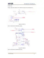
Figure 4-13 User Button
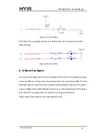
MYS-6ULX-IOT is equipped with two user LEDs.Please refer to the schematic of the
LEDs as below.
Figure 4-14 User LEDs
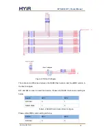
4.12 Boot Configure
The boot process begins at the Power-On Reset (POR) where the hardware reset logic
forces the ARM core to begin the execution starting from the on-chip boot ROM. The boot
ROM code uses the state of the internal register BOOT_MODE[1:0] as well as the state of
various eFUSEs and/or GPIO settings to determine the boot flow behavior of the device.
MYS-6ULX-IOT is equipped with a 4 bit switch to change the boot device.
Please refer to the schematic for the boot state as below,


