


113903G -System Installation Manual
33
D
IRECTIONS FOR
W
ALL
M
OUNTING USING
S
TRUT
C
HANNEL
SYSTEMS WITH THREE BATTERY CABINETS
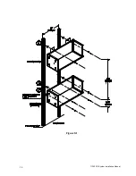
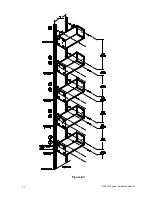
Refer to Figure 8.3.
•
Three Battery Cabinet mounting requires (12) Spring Clamp-nuts, (12) ¼-20 Bolts
and (12) ¼-20 Flat Washers.
•
Electronics Cabinet mounting requires (2) Spring Clamp-nuts, (2) ¼-20 Bolts and (2)
¼-20 Flat Washers.
1) Mount Strut Channels to wall vertically (hardware not included), 16” apart on center.
(
NOTE:
Strut Channels are long enough for four Battery Cabinets and maybe cut to
desire length;
Do Not
cut strut channels shorter than 43 inches.)
2) Place one spring clamp-nut on each strut channel 2.5” from the bottom of the strut
channels.
3) Place the next spring clamp-nuts 5.438” on center above the spring clamp-nuts
placed in step #2.
4) Place the next spring clamp-nuts 4.683” on center above the spring clamp-nuts
placed in step #3.
5) Place the next spring clamp-nuts 5.438” on center above the spring clamp-nuts
placed in step #4.
6) Place the next spring clamp-nuts 4.683” on center above the spring clamp-nuts
placed in step #5.
7) Place the next spring clamp-nuts 5.438” on center above the spring clamp-nuts
placed in step #6.
8) Place the next spring clamp-nuts 14.37” on center above the spring clamp-nuts
placed in step #7.
9) Remove cover from Electronics Cabinet and Battery Cabinets.
10) Line up the four holes on the back of Battery Cabinet #1 with the spring clamp-nuts
from steps #2 and #3. Secure Battery Cabinet #1 to the spring clamp-nuts using (4)
¼-20 bolts and (4) flat washers.
11) Remove the top left front knockout from Battery Cabinets #1, #2 and #3.
12) Remove the bottom left front knockout from Battery Cabinets #2 and #3.
13) Place Battery Cabinet #2 on top of Battery Cabinet #1. Line up the four holes on the
back of Battery Cabinet #2 with the spring clamp-nuts from steps #4 and #5. Secure
Battery Cabinet #2 to the spring clamp-nuts using (4) ¼-20 bolts and (4) flat
washers.
14) Place Battery Cabinet #3 on top of Battery Cabinet #2. Line up the four holes on the
back of Battery Cabinet #3 with the spring clamp-nuts from steps #6 and #7. Secure
Battery Cabinet #3 to the spring clamp-nuts using (4) ¼-20 bolts and (4) flat
washers.
15) Remove the bottom left front knockout from the Electronics Cabinet.
16) Place Electronics Cabinet on top of Battery Cabinet #3. Line up the two holes on the
back of the Electronics Cabinet with the top two spring clamp-nuts. Secure the
Electronics Cabinet to the spring clamp-nuts using (2) ¼-20 bolts and (2) flat
washers.
(Verify that the knockout from each cabinet line up with the other
cabinet.)
Return to Chapter 4 “Inverter Module and Battery Module Assembly”
Содержание Illuminator System CM Series
Страница 31: ...113903G System Installation Manual 30 Figure 8 1 ...
Страница 33: ...113903G System Installation Manual 32 Figure 8 2 ...
Страница 35: ...113903G System Installation Manual 34 Figure 8 3 ...
Страница 38: ...113903G System Installation Manual 37 Figure 8 4 ...
Страница 39: ...113903G System Installation Manual 38 ...


