2201Q4JE-MY-C9-N_2018.01.
Chapter 5 Maintenance and Inspection
Compound 2-stage Screw Compressor
4032**C
5.5 Reassembly
5-42
5.5.7 Balance Piston and Balance Piston Sleeve
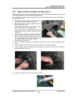
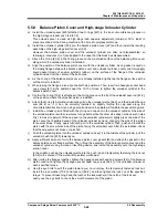
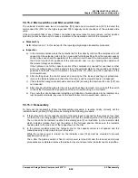
Install the balance piston sleeve to the high-stage suction cover, and install the balance piston on the M
rotor shaft end portion of the high-stage suction cover side.
The installation of the balance piston sleeve may be done either before the suction cover installation to
the main rotor casing.
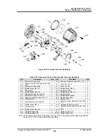
a) First install the internal snap ring [37] for the O-ring
spacer [36], and then install the spacer [36].
b) After setting the O-ring [35] in position, install the
balance piston sleeve [33].
Insert the chamfered side of the balance piston
sleeve towards the O-ring already placed.
Also, align the notch of the balance piston sleeve
to the spring pin [34] for rotation stop and to the oil
supply port.
c) Insert the snap ring [37] to retain the balance
piston sleeve. As it should be difficult to fit the snap
ring into the groove due to the elastic force of the
O-ring, either push the side of the ring by a guide
bar or tap the head of the guide bar to fit the
ring securely into the groove.
d) Confirm the balance piston key [31] attached on the M rotor shaft end of the high-stage suction
cover.
e) Push the balance piston [30] into the high-stage suction cover using two eyebolts.
f) Install the snap ring [32] using external snap ring pliers and retain the balance piston. Confirm the
snap ring fitted into the groove.
g) Install the O-ring [73-2] on the unloader push rod [67-2].

