2201Q4JE-MY-C9-N_2018.01.
Chapter 5 Maintenance and Inspection
Compound 2-stage Screw Compressor 4032**C
5.4 Disassembly and Inspection
5-13
5.4
Disassembly and Inspection
During the overhaul work, be very careful in handling the parts. As the compressor is a delicate
machine that is operated at very high speed, a minor handling error could result in a situation where the
rotor and other major components must be entirely replaced. Another possibility is that it may cause a
failure or performance degradation when the compressor is operated after the reassembly.
Please fully understand the following sections before starting the work.
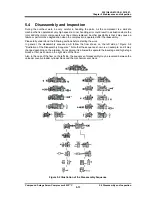
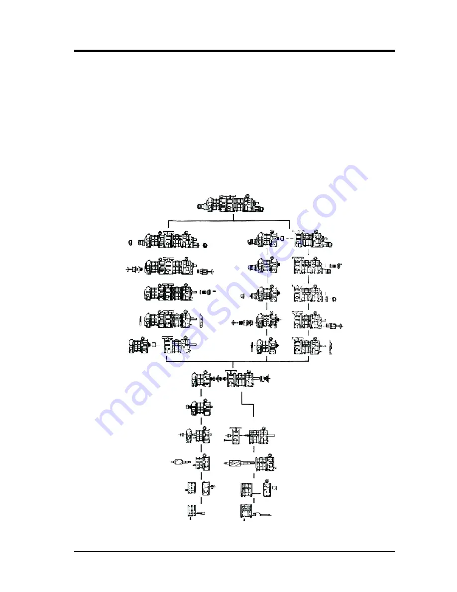
In general, the disassembly sequence will follow the flow shown on the left side of Figure 5-2
"Illustration of the Disassembly Sequence". Note that the sequence shown is an example, and it may
change depending on the situation. For example, it is allowed to separate the low-stage and high-stage
blocks at first, as shown on the right side of the flow.
Also, in the case of the flow on the left side, the sequence of disassembly may be reversed between the
unloader cover/unloader cylinder block and the mechanical seal block.
Figure 5-2 Illustration of the Disassembly Sequence

