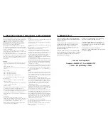
background image

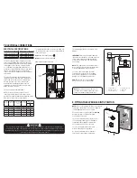
6. PLUMBING CONNECTIONS 

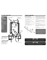
The 8 arrows depict water 

and electrical entry points

Location holes for 

mounting are easily 

marked off from inside 

unit

Bottom fi xing position

Left hand 

water entry 

sealing cap

and clip

NOTE!

PLUMBING THE 

SHOWER UNIT MUST 

PROCEED WIRING!

QI

QUICK INSTALLATION
As you can see from the 

diagram right the shower 

unit can be both plumbed 

and wired from 8 different 

positions;

n

  Top right

n

  Top left

n

  Bottom right

n

  Bottom left

n

  Right side

n

  Left side

n

  Rear right

n

  Rear left

IMPORTANT

Before turning on the water supply to the shower unit the water supply pipe should be fl ushed out to remove 

debris. After fl ushing the pipework ensure that the shower unit is positioned squarely on the wall and tighten 

the screws. Tighten all plumbing connections and check the pipework for leaks.

IMPORTANT

To comply with water regulations, building regulations or any specifi c local water company regulations and 

should be in accordance with BS EN 806. A double check valve must be fi tted with all fl exible 

shower accessories where it is possible that the showerhead may come into contact with used water 

i.e. In the bath or shower tray.

!

!

!

!

!

!

!

!

PLUMBING CONNECTIONS 

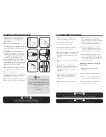
Water inlet direction option


The shower unit is supplied for right hand installation. 

To plumb the unit on the left you must:

1.  Pull the metal retaining clip out of the blanking end 

cap with a pair of pliers.

2. Remove the blanking cap - pull off.

3.  Simply refi t blanking cap to the inlet pipe on the 

right hand side of the unit.

4.  Re-insert the metal fi xing clip ensuring it is pushed 

fi rmly into the groove. 

5.  When leak testing the installation you must ensure 

there are no leaks from this area.

Turn off the water supply at the isolating stop tap. 

Having determined the direction of the inlet water 

supply: Top (falling), Bottom (rising), or Back inlets. It 

is necessary to remove the appropriate plastic cross 

section from the back plate, before commencing with 

the installation.

We have incorporated into the bottom right & left-

hand side of the back plate easy removable trim 

sections to allow easy access when connecting the 

water supply.

(Please Note! Remember to replace this trim section 

before refi tting the cover).

Connect the mains water supply to the inlet of the 

shower unit using a 15mm copper, stainless or plastic 

pipe with a 15mm compression elbow or 15mm 

push-fi t elbow.

Do not use excessive force when making the 

connection to the unit.

DEFAULT PLUMBING SETTING

The shower unit is supplied for right hand 

installation. To plumb the unit on the left you must 

remove the blanking cap and refi t it to the inlet pipe 

on the right hand side of the unit ensuring the metal 

fi xing clip is pushed fi rmly into the groove. When 

leak testing the installation you must ensure there 

are no leaks from this area.

Removable cover plates for left or 

right and bottom inlets, accessible 

once cover plate is removed. 

These simply slide into place 

before replacement of cover.

Water inlet, this can be switched 

with the cap and fi xing clip 

opposite to change water input 

direction.

See next page for instruction.

Содержание Solo QI

Страница 1: ...Instantaneous Electric Shower Installation Instructions IMPORTANT ThisStep by Stepguideshouldbegiventothecustomer afterinstallationanddemonstration ...

Страница 2: ...t risk provided they are installed used and maintained in good working order in accordance with our instructions and recommendations WARNING DO NOT operate shower if frozen or suspected of being frozen It must thaw out before using DO NOT operate the unit if the showerhead or spray hose becomes damaged DO NOT restrict flow out of shower by placing showerhead in direct contact with your body DO NOT...

Страница 3: ... are fully tightened and that no cable insulation is trapped under screws Ensure the cable clamp is used to secure the cable The earth continuity conductor of the electrical installation must be effectively bonded to earth on the fuse board CAUTION Check there are no hidden cables or pipes before drilling holes for wall plugs Exercise great care when using power tools near water The use of a resid...

Страница 4: ...offattheisolatingswitchwhennot inuse 3 GENERALADVICETOSHOWERUNITUSERS Thefollowingpointswillhelpyoutounderstandhow yourMXshowerunitoperates Theflowrateofwaterpassingthroughtheshower unitdeterminesthewatertemperature Thelowerthe flowthewarmerthewater thehighertheflowthe coolerthewater Thetemperatureproducedbytheshowerunitwill varybetweenseasonsonanyonesettingofthe temperaturecontrol Thisisduetovari...

Страница 5: ...ren with reduced physical sensory or mental capabilities or lack of experience and knowledge unless they have been given supervision or instruction concerning use of the appliance by a person responsible for their safety Children should be supervised to ensure that they do not play with the appliance 5 INSTALLATION Positionyourshowerunitonthewallawayfromthe directsprayoftheshowerandataboutthesame ...

Страница 6: ...pulloff 3 Simplyrefitblankingcaptotheinletpipeonthe righthandsideoftheunit 4 Re insertthemetalfixingclipensuringitispushed firmlyintothegroove 5 Whenleaktestingtheinstallationyoumustensure therearenoleaksfromthisarea Turnoffthewatersupplyattheisolatingstoptap Havingdeterminedthedirectionoftheinletwater supply Top falling Bottom rising orBackinlets It isnecessarytoremovetheappropriateplasticcross s...

Страница 7: ...8m 9 5 39 58amps 40amps 40amps 21m 32m 10 5 43 75amps 45amps 45amps 18m 30m Nominal Power rating at 240V 7 5kW 32A MCB rating 8 5kW 40A MCB rating 9 5kW 40A MCB rating 10 5kW 45A MCB rating Nominal Power rating at 230V 6 9kW 32A MCB rating 7 8kW 40A MCB rating 8 7kW 40A MCB rating 9 6kW 45A MCB rating L N E Terminal block 1 Terminal block 2 Power neon 3 Right microswitch 4 Left microswitch 4 5 7 6...

Страница 8: ... double pole isolating switch 2 Turn the top power selector knob to the Cold setting Solid Blue Symbol 3 Turn the bottom temperature control knob anti clockwise to the full cold position 4 Ensuring the water supply is fully on at the mains stop cock and isolating service valve if fitted check that water is not leaking from the bottom of the case 5 Switch on the electrical supply at the double pole...

Страница 9: ... the temperature control knob anti clockwise this will increase the flow of water and decrease the shower temperature 6 To turn off the shower unit turn the power selector knob to the OFF position 7 A small amount of water will be retained in the showerhead after the shower has been turned off This may drain over a few minutes 8 Switch of pull cord or wall mounted switch WARNING IF RE STARTING THE...

Страница 10: ...system Oncethishas beencarriedoutyouwillneedtofitanew pressurereliefdevice Contacttheservice lineon 2 Checkmainswaterconnections 3 Cleantheshowerheadofanydirtanddebris andifnecessaryreplacetheshowerhead andhose Oncethishasbeencarriedoutyou willneedtofitanewpressurereliefdevice Contacttheservicelineon Q Thefilterorshowerheadkeepsblockingorfilling upwithsolidmaterials A Aftertheinitialinstallationno...

Страница 11: ...defects Itdoesnotapplytonormalwearandtear accidentaldamage inappropriateuse includinginappropriatecleaning orotherevents outsidethemanufacturer scontrol 7 Thisguaranteeappliesonlytotheproductitselfandasaresultany liabilityattributedtoMXGroupislimitedtothecostofthecomponent 8 IfaproductisdeemedtobeoffaultymanufactureMXGroupwillat theirdiscretionreplacethecomponent Anyrelatedconsequential lossordama...

Страница 12: ...NOTES NOTES ...
Страница 13: ...roup com CUSTOMERCARE 08455052211 TRADE DESCRIPTIONS ACT Variations in terms of colour finish materials and all other aspects of appearance may occur on occasions either through non availability of materials or due to our policy of continuing technical improvement Therefore the Company reserves the right to change specification or withdraw products from this list without prior notice being given ...

Отзывы: