SH - NLFREN - v1.1 - 01122016
5
NL
TOOLS
10
distance to the floor of
between 0.8
m
and
1.5 m (see
dia.
3, above).
f) Insert the load hook into the hook bracket
of
the mounting
casing when
using
the
additiona
l
load hook
with
deviating
shaft.
g)
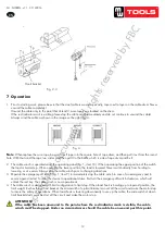
The electric pulley will be attached at the top. Attach the pulley with bearer frame on the
crossbar. The girder is then attached to the support columns. The support columns must be, in
accordance with the requirements of the customer, properly secured onthe working area. The
support columns must be installed to be sturdy and stable. Also be able to withstand a nominal
load long-term.
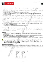
Dia.2
Dia
.3
Hook bracket
Operation
a
) Prior to
starting work,
please be
sure
that the
steel cable
is
wound
up
exactly,
layer next to
layer
on
the cable drum. Never unwind the cable completely!
Unwind the
cable only
to the point that
at
least
3
more layers
are
located
on
the drum.
If the red indicator mark is
visible
,
please stop
the
cable winch
immediately and do not
continue
to
unwind the
cable!
Always
wind
the
cable as shown
in the image
on
the right
,
dia
.
4.
Dia.4
Note: When replace the wire rope
,
be sure to pull rope into the
square
hole
of
rope drum, and then
pull it out from the round hole. With that
wind
the rope two circles and then pull it to the baffle which
is side of rope drum and fix it.
b) The
cable winch
is
operated
using the
operating
panel (dia. 1, item 10). When
operating
the
upper position
of
the switch, the load is hoisted up.
When operating
the lower position, the load is
lowered. Never
switch
directly from hoisting to lowering
or vice versa.
Always
stop
the
cable winch
prior
to
changing
directions.
c )
Operate the Emergency-Off
switch (dia.
1, item
9)
to immediately
stop
the
cable winch
in
case
Haakhouder
Afb. 2 - 3
10
distance to the floor of
between 0.8
m
and
1.5 m (see
dia.
3, above).
f) Insert the load hook into the hook bracket
of
the mounting
casing when
using
the
additiona
l
load hook
with
deviating
shaft.
g)
The electric pulley will be attached at the top. Attach the pulley with bearer frame on the
crossbar. The girder is then attached to the support columns. The support columns must be, in
accordance with the requirements of the customer, properly secured onthe working area. The
support columns must be installed to be sturdy and stable. Also be able to withstand a nominal
load long-term.
Dia.2
Dia
.3
Hook bracket
Operation
a
) Prior to
starting work,
please be
sure
that the
steel cable
is
wound
up
exactly,
layer next to
layer
on
the cable drum. Never unwind the cable completely!
Unwind the
cable only
to the point that
at
least
3
more layers
are
located
on
the drum.
If the red indicator mark is
visible
,
please stop
the
cable winch
immediately and do not
continue
to
unwind the
cable!
Always
wind
the
cable as shown
in the image
on
the right
,
dia
.
4.
Dia.4
Note: When replace the wire rope
,
be sure to pull rope into the
square
hole
of
rope drum, and then
pull it out from the round hole. With that
wind
the rope two circles and then pull it to the baffle which
is side of rope drum and fix it.
b) The
cable winch
is
operated
using the
operating
panel (dia. 1, item 10). When
operating
the
upper position
of
the switch, the load is hoisted up.
When operating
the lower position, the load is
lowered. Never
switch
directly from hoisting to lowering
or vice versa.
Always
stop
the
cable winch
prior
to
changing
directions.
c )
Operate the Emergency-Off
switch (dia.
1, item
9)
to immediately
stop
the
cable winch
in
case
Afb. 4
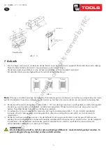
7 Gebruik
1. Voor het begin van het werk, maak zeker dat de kabel correct op de trommel is opgerold. Ontrol de kabel nooit volledig!
Ontrol de kabel totdat er tenminste 3 omwentelingen op de trommel blijven.
Als de rode markering zichtbaar is, stop de takel onmiddellijk, en ontrol de kabel niet verder!
Rol altijd de kabel op zoals afgebeeld aan de rechterkant van afbeelding 4.
Nota
: Wanneer u de kabel vervangt, trek deze door het vierkante gat van de trommel, en trek hem vervolgens door het ronde
gat. Rol de kabel met twee omwentelingen om de trommel op, trek hem dan aan de zijkant van de trommel en bevestig hem.
2. De takel wordt vanaf de sturingsdoos bediend (afb. 1, 10). Als de knop naar boven wordt gedrukt, wordt de last opgetild.
Als de knop naar beneden wordt gedrukt, wordt de last neergelaten. Schakel nooit direct van de ene positie naar de
andere. Stop altijd de takel alvorens van richting te veranderen.
3. In noodgeval, of om een herstarten te voorkomen, druk op de noodstop knop (afb. 1, 9), om de takel onmiddellijk
te stoppen. Om de takel opnieuw te kunnen gebruiken, draai de noodstop knop naar rechts, om de rode sleutel te
ontgrendelen.
4. De takel is met twee aanslagen voorzien. Als de lasthaak tot de hoogste positie komt, raakt het gewicht de bovenste
aanslag. De microschakelaar van de bovenste aanslag onderbreekt de stroomtoevoer en stopt de motor, om de veiligheid
te garanderen. Als de lasthaak naar beneden gaat, en de kabel bijna ontrold is, wordt de stroomtoevoer door de
microschakelaar onderbroken, om de motor te stoppen.
AANDACHT!
Als de kabel zo ontrold is, dat de rode markering zichtbaar is, moet de takel gestopt worden. In
geen ieder geval mag de kabel verder ontrold worden.
Afstandbediening
Afstand met de grond
0,8 - 1,5 m
Fout Fout Correct
copyrighted
document
- all
rights
reserved
by
FBC


