9
W-DMX G4 system
1
3
2
4
Fig.3
1.4 INSTALLATION
BLACKBOXF1G4MK2
1. Choose one of the following options to make the DMX connection:
• Connect the DMX source to the XLR 5 pin DMX IN port (BlackBox only) or the to the RJ 45 DMX IN
port.
• Connect the DMX fixture to the XLR 5 pin DMX OUT port (BlackBox only) or the RJ 45 DMX OUT port.
• Unit with optional Ethernet lighting protocol support: Connect the Ethernet lighting source or out-
put to the Ethernet in port.
2. Attach the supplied standard antenna(s) and standard adapter(s) or other suitable antenna(s) /
adapter(s) available to the matching connector(s).
3. Choose one of the following options to connect power to the unit:
• Attach a suitable mains plug to the supplied power cord and connect the power supply to the AC
power input.
• Connect the power supply to the DC power input.
4. If required, attach the unit to the supplied mounting brackets or other mounting hardware available.
WHITEBOXF1G4
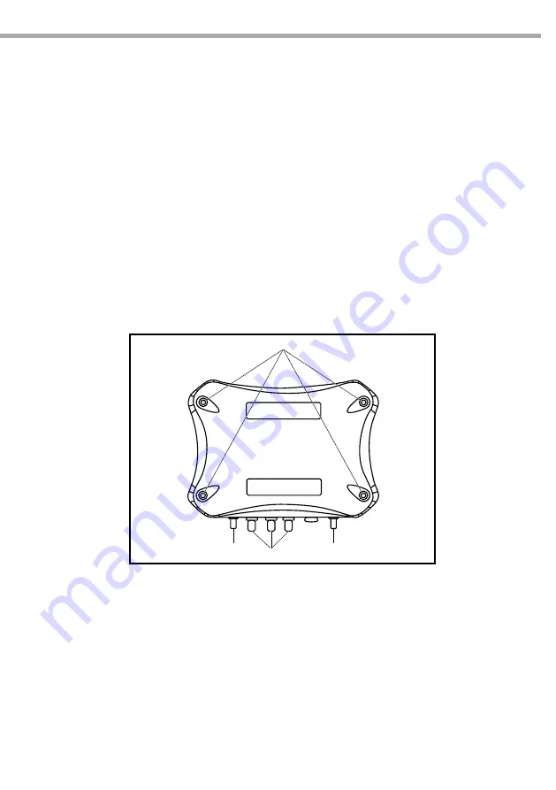
When connecting a WhiteBox model it is necessary to open the housing.
1. Unscrew the housing by the 4 screws (1).
2. Open the housing.
3. Loosen the cord strips (3) by turning the screws counter-clockwise.
4. Put the cables through the cord strips (3).
5. When using AC, put the AC power cables into the socket (see page 7) and tight the bolts of the socket.
6. Couple the connectors to the cables:
• When using 12 V DC power, couple the 12 V DC power cable to the Phoenix Gold connector.
• Couple RJ 45 connector to DMX signal cable (or Ethernet cable if option is installed and should be
used).
7. Fit the connectors within the sockets (see page 7).
8. Fit the cord strips by turning them clockwise.
9. Close the housing and fit the 4 screws (1) by turning them clockwise.


