MGS Installation and Operation Manual
1000-0085 Rev 0
9
2.1. General Placement Guidelines
NOTE:
The MGS should be installed plumb and level and securely
fastened to a rigid mounting surface.
Sensors must be located within the appropriate wire lengths from the central
control unit (if used).
In all cases the sensor supplied is designed for maximum sensitivity to a
particular gas. However, in certain circumstances false alarms may be caused
by the occasional presence of sufficiently high concentrations of other gaseous
impurities. Examples of situations where such abnormalities may arise include
the following:
•
Plant room maintenance activity involving solvent or paint fumes or
refrigerant leaks.
•
Accidental gas migration in fruit ripening/storage facilities (bananas -
ethylene, apples - carbon dioxide).
•
Heavy localised exhaust fumes (carbon monoxide, dioxide, propane)
from engine-driven forklifts in confined spaces or close to sensors.
Murco recommends setting the alarm delay to minimise false alarms.
2.2. Components and Access Overview
NOTE:
The wiring is the same for the electro-chemical, semi-
conductor, and infrared models. The controller wiring is the same
for all controllers.
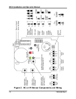
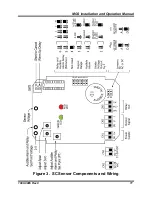
There is a 5-minute power-up delay to allow the sensor to stabilise. Refer to
Figure 2 and Figure 3 for internal components and wiring.
Содержание MGS
Страница 10: ...MGS Installation and Operation Manual 10 1000 0085 Rev 0 Figure 2 EC or IR Sensor Components and Wiring ...
Страница 11: ...MGS Installation and Operation Manual 1000 0085 Rev 0 11 Figure 3 SC Sensor Components and Wiring ...
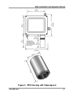
Страница 17: ...MGS Installation and Operation Manual 1000 0085 Rev 0 17 Figure 5 IP66 Housing with Splashguard ...


