MGS Installation and Operation Manual
24
1000-0085 Rev 0
Bump Test
Exposing the sensor to a gas and observing its response to
the gas. The objective is to establish if the sensor is reacting
to the gas and all the sensor outputs are working correctly.
There are two types of bump test.
Quantified:
A known concentration of gas is used.
Non-Quantified:
A gas of unknown concentration is
used.
Calibration
Exposing the sensor to a calibration gas, setting the “zero” or
standby voltage to the span/range, and checking/adjusting all
the outputs, to ensure that they are activated at the specified
gas concentration.
CAUTION:
Before you carry out the test or calibration:
•
Advise occupants, plant operators, and supervisors.
•
Check if the MGS is connected to external systems such as
sprinkler systems, plant shut down, external sirens and
beacons, ventilation, etc. and disconnect as instructed by the
customer.
•
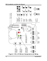
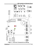
Deactivate alarm delays if selected at JP5, JP6 as per Figure
2 and Figure 3.
•
For bump test or calibration the MGS should be powered up
for 24 hours. The instrument should be fully stabilised per
Section 4.
6.2. Bump Testing
After installation, the units should be bump tested. Expose the sensors to
appropriate test gas (NH
3
, CO
2
, etc.). The system will alarm when the test gas
ppm value is above the alarm level. The gas should put the system into alarm
and light the red LED. The delay prevents the audible alarm from sounding
and the relay from switching (if delay is set).
With a bump test you can see the functions of the sensor - the red LED will
light, the relay and audible alarm will function, and the output (0-10V, for
example) will show the gas level.
Ideally bump tests are conducted on site in a clean air atmosphere.
Содержание MGS
Страница 10: ...MGS Installation and Operation Manual 10 1000 0085 Rev 0 Figure 2 EC or IR Sensor Components and Wiring ...
Страница 11: ...MGS Installation and Operation Manual 1000 0085 Rev 0 11 Figure 3 SC Sensor Components and Wiring ...
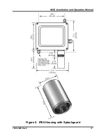
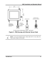
Страница 17: ...MGS Installation and Operation Manual 1000 0085 Rev 0 17 Figure 5 IP66 Housing with Splashguard ...

