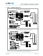
MTIC Installation & Operation Manual
MTIC Manual R6
Page 9 of 18
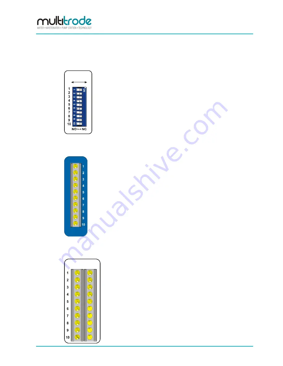
2.2 Output Relay DIP Switches
This section is
black
in colour on the rear panel.
SELECT
FUNCTION
see fig #1
Figure 4
– Output Relay DIP Switches
Setting a DIP switch to the left or right makes the corresponding output
relay act as a normally closed or normally open contact under the
following condition:
Power is supplied to the unit and no liquid covers the corresponding
sensor.
2.3
Probe Inputs
This section is
blue
in colour on the rear panel.
PROBE
INPUTS
see fig #3
Figure 5
– Probe Inputs
A MultiTrode probe would be the normal method of level detection.
Connection of ball floats is also accomplished via these terminals,
although this is not recommended for reliable level detection.
2.4 Output Relays
This section is
white
in colour on the rear panel.
OUTPUTS
see fig #1
Figure 6
– Output Relays
10 programmable contacts allow for the switching of contactors or other
equipment. Each relay is rated at 240VAC 5 Amp resistive or 2 Amp
inductive.
The operation of the devices is controlled by level switch points hardwired
to the appropriate output relay. This sets the levels at which the devices
activate and de-activate.


