MTIC Installation & Operation Manual
MTIC Manual R6
Page 11 of 18
4
Mounting
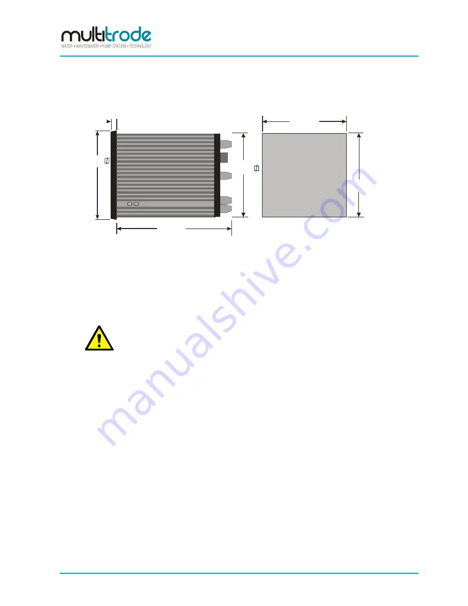
Mount the MTIC into a 91.0mmx 91.0mm hole (see drawing). The clamp brackets will allow installation
into panels up to 8mm (absolute max.) thickness.
PANEL
CUT OUT
DEMENSIONS
PLAN ( TOP VIEW )
CUT OUT ELEVATION
( TOP VIEW )
92mm
120mm
92mm
91mm
8mm
97mm
Figure 10
– Plan and elevation views of the MTIC
Slide the controller in from the front of the panel.
Insert the two clamp brackets into the double slots in the top and bottom of the case (see
drawing).
Tighten the screws sufficiently to hold unit.
NOTE:
Over-tightening will deform the clamps.


