2
6
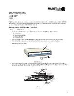
Secure the DSU to the base using the two plastic mounting screws provided in the upgrade kit. One of
the screws goes into the connector and the other one into the standoff on the motherboard.
7
Set switch position 2 of the 8-position DIP-switch to the OPEN (UP) position.
8
Slide the cover onto the base and replace the four cover screws.
9
Attach the internal DSU serial tag to the bottom of the MultiMux cabinet next to the existing serial tag(s).
10 Connect the RJ48 cable provided in the upgrade kit to the COMPOSITE LINK INTERNAL DIGITAL DSU
connector on the backpanel of the MultiMux.
11 Connect the other end of the RJ48 cable into a telephone wall jack and plug in the power cord.
12 Refer to Chapter 5 of your MultiMux Owner's Manual to configure your internal DSU.
MMV1600/3200 Series DSU Upgrade Procedure
Step
Procedure
1
Check the contents of your upgrade kit to ensure that it contains the parts listed below:
a) Screwdriver
b) Mounting screws (2)
c) MMH1656K DSU
d) Serial tag label
2
Turn the MultiMux power switch to OFF and unplug the MultiMux power cord from the wall outlet.
3
Loosen the four quarter-turn-fasteners on the front panel and remove the front panel.
4
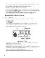
Loosen the two pc board chassis lock screws on the back panel.
PC Board Chassis Lock Screws
5
Pry up on the two pc board chassis lock screws to unlock the pc boards in the chassis. Temporarily
retighten these screws while in the up position.
6
Disconnect the pc board power cable from the power supply.
7
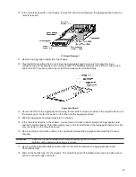
Partially pull out all the pc boards in the chassis just past the inside edge of the data and address ribbon
cable connectors. It may require a slight forward tug on the voice/fax board (if installed) to free it from its
board edge connector while pulling the other boards forward.
8
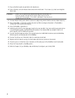
Disconnect the control ribbon cable from the Aggregate board.
9
Disconnect the data and address ribbon cable connector from the Aggregate board.


