background image

PAGE 10 — ST-2010 SERIES SUBMERSIBLE PUMPS — OPERATION & PARTS MANUAL  — REV. #1 (12/15/05)

ST-2010 SERIES  SUBMERSIBLE  PUMPS 

 GENERAL INFORMATION

Introduction

The Multiquip Model ST-2010 submersible pump is designed to
pump water and is used for the draining (de-watering) of
swimming pools, well casings construction sites, cofferdams,
manholes, transformer vaults and excavations. The ST-
2010TCUL is designed for heavily debris-laden water and the
2-inch discharge port can handle solids up to one inch in
diameter.

A cast iron ductile type impeller is attached to the output shaft of
a 1 HP electric motor which provides adequate power for general
purpose pumping. This submersible pump is supplied complete
with an electric power cable, and a discharge port which accepts
a 2-inch hose.

This pump is ideal for portability because of its light weight and
carrying handle. For reliability and long life, a mechanical seal
provides shaft sealing, with an oil chamber separating the pump
section from the motor.

The pump when in use, should be installed as free standing
(upright position) on its strainer base. A  2-inch discharge hose
(not supplied) should be connected to the discharge port . The
discharge hose should be adequately supported to avoid stress
on the pump.

For maximum water flow, the discharge hose should be kept as
short as possible, and with minimum elevation above the pump.
Remember as the length and/or height of the discharge hose is
increased, the flow of water will be reduced. Also any reduction
in the hose size, and any fittings such as valves or outlet nozzles,
will restrict the water flow.

To avoid back-siphonage when the pump is switched off, ensure
that the end of the discharge hose is installed above the water
level at the final discharge point.

When the pump is switched off, the water remaining in the hose
will run back through the pump. This can be avoided by placing
a non-return valve in the hose nearest the pump.

NEVER

 use this submersible pump to pump flammable liquids

or operate in a explosive or flammable environment.

Avoid using this pump in conditions where mud, grit, silt or other
debris are present. These conditions could cause blockage and
cause excessive pump wear.

DO NOT

 install the pump directly into an area where there is a

heavy build-up of mud, grit, silt or debris. If this condition is present,
install the pump on a platform before operating.

This pump must always be positioned on a platform in an upright
position. 

NEVER 

operate the pump by a suspended rope. To

prevent large solids from entering the pump, install a wire mesh
screen or similar barrier around the pump.

If the pump was used to pump water containing mud, silt, use
clean water to flush out the pump after each use.

DO NOT

 allow the pump to run dry, as this will damage the

pump. During maintenance, dry running is permissible but only
for a few seconds.

NEVER

 lift the pump by its electrical power cord.

 ALWAYS

 lift

the pump by its carrying handle or attach a rope to the carrying
handle.

A pump fully submerged pump in liquid will not freeze, unless
the liquid freezes. 

DO NOT 

allow a partially submerged pump to

freeze. The expansion of water freezing in the volute may crack
the pump, causing expensive repairs. If there is any danger of
the pump being subjected to freezing temperatures, Lift the pump
from water and allow it to drain thoroughly.

If the pump jams or the pump rotor locks for any reason,
disconnect the pump from the power source immediately.
Allowing the pump motor to cycle 

ON

 and 

OFF

 under an overload

condition can burn out the motor.

When replacement of nuts and bolts is required, use only
recommended parts as referenced in the parts section of this
manual. This pump uses 

metric

 threads. 

DO NOT

 use English

measurement threads.

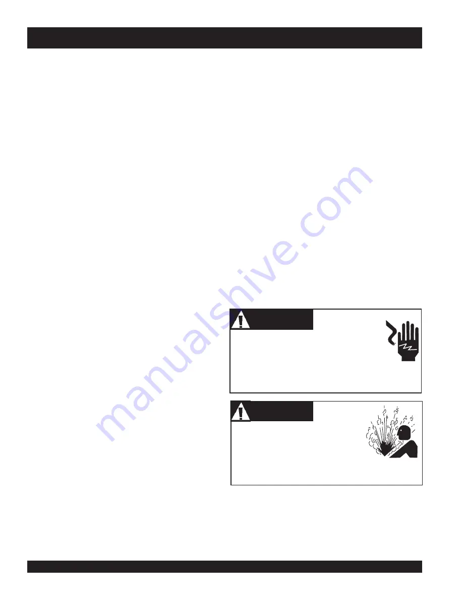
Control Box Installation Warnings

Failure to follow the above referenced precautions could result
in serious injury or death! Replace pump cord immediately if
cord becomes damaged or severed. This pump must be installed
in accordance with National Electric Code ANSI/NFPA 70 so as
to prevent moisture from entering or accumulating with the boxes,
conduit bodies fittings, float housing or cable.

When installing the control box, the possibility
exists of 

electrical


shock

electrocution

 and

possibly 

death!  NEVER 

have untrained

personnel perform the installation. 

ALWAYS

 have

qualified service personnel (licensed electrician) perform the
installation.

Explosion

 or 

Fire Hazard 

exists if this

pump is used with 

flammable liquids

DO

NOT

 use this pump with 

flammable

liquids

DO NOT

 install this pump in

hazardous locations as defined by the National Electrical
Code, ANSI/NFPA 70.

DANGER

DANGER

DANGER

DANGER

DANGER

WARNING

WARNING

WARNING

WARNING

WARNING

Discount-Equipment.com

Содержание ST-2010 Series

Страница 1: ...RATION AND PARTS MANUAL Revision 1 12 15 05 Submersible Pumps Model ST 2010 Series THIS MANUAL MUST ACCOMPANY THE EQUIPMENT AT ALLTIMES www discount equipment com D i s c o u n t E q u i p m e n t c o...

Страница 2: ...ie Terex JLG MultiQuip Mayco Toro Stone Diamond Products Magnum Airman Mustang Power Blanket Nifty Lift Atlas Copco Chicago Pneumatic Allmand Brothers Essick Miller Spreader Skyjack Lull Skytrak Tsuru...

Страница 3: ...Alert Symbols 5 Rules For Safe Operation 6 7 Dimensions 8 Specifications Pump Control Box 9 General Information 10 Components 11 Float Switches 12 Float Switch Piggy Back 13 Float Switch Control Box...

Страница 4: ...referenced with Hazard Symbols which appear throughout this manual and will be referenced in conjunction with Safety Message Alert Symbols Rotating Parts NEVER operate equipment with covers or guards...

Страница 5: ...ase for normal operation The ST 2010B submersible pump requires 230 VAC 60 Hz single phase DO NOT restrict the flow of the discharge hose as it may cause overheating Be careful of discharge whipping u...

Страница 6: ...T attempt to thaw out a frozen pump by using a torch or other source of flame Application of heat in this manner may heat the oil in the seal cavity above the critical point causing pump damage DO NOT...

Страница 7: ...SUBMERSIBLE PUMPS DIMENSIONS Figure 1 ST 2010 Series Dimensions 23 82 in 605 mm 10 23 in 260 mm 3 14 in 80 mm 5 11 in 130 mm NPT 2 4 52 in 115 mm 3 54 in 90 mm 7 08 in 180 mm 4 37 in 111 mm 49 21 ft...

Страница 8: ...e t u n i m s r e t i l 0 6 3 r e t e m a i D s d i l o S x a M m m 5 2 n i 0 0 1 d a e H x a M s r e t e m 7 6 1 t f 5 5 s r e t e m 7 6 1 t f 5 5 s r e t e m 7 3 1 t f 5 4 r e w o P w k 5 7 0 P H 0...

Страница 9: ...here is a heavybuild upofmud grit siltordebris Ifthisconditionispresent install the pump on a platform before operating Thispumpmustalwaysbepositionedonaplatforminanupright position NEVER operate the...

Страница 10: ...charge hose to avoid stress on the pump 5 AC Power Cable This unit is supplied with an AC power cable Always check the cable for signs of wear NEVER use a defective power cable Replace the cable immed...

Страница 11: ...he all steel mercury switch is held by positioning pins Interior is filled with cell foam Suitable for most liquid environments Hermetically sealed Thick walled non corrosive PVC plastic enclosure Pre...

Страница 12: ...ication ST 2010SERIES SUBMERSIBLE PUMPS FLOATSWITCH PIGGY BACK Figure 6 Single Float Switch Application Diagram Figure 6 shows a single float switch application For dual float switch capabilityuseaMod...

Страница 13: ...r resistant control box provides watertight housing and glands to prevent water from leaking into the box andafloatswitchinterface WhenusingtheCB3controlbox onlytheSW 1WOPfloatswitch 2 canbeused noplu...

Страница 14: ...RSIBLE PUMPS OPERATION PARTS MANUAL REV 1 12 15 05 PAGE 15 Figure 8 CB6 Control Box and Dual Float Switch Application Diagram ST 2010SERIES SUBMERSIBLE PUMPS FLOATSWITCH CONTROLBOX D i s c o u n t E q...

Страница 15: ...mersible Pump Upright Position Correct 2 Makesurethepumpisalwaysplacedinanuprightposition nottilted Figure10 Neverpositionthepumpdirectlyona soft loosebottom Remembertoattainmaximumpumping capacityand...

Страница 16: ...hecable from pulling out of the terminal block and also prevent moisture from entering the control box 3 Determine the length of the float switch wires then secure float switch wires to pump discharge...

Страница 17: ...ree wires Each wire is color coded The colors are WHITE BLACK and GREEN Itisrecommendedthatthepowerbeing supplied to the control box ALWAYS beconnectedtoacircuitbreakeror a quick disconnect switch Thi...

Страница 18: ...connectingpowerfrom thepump 2 Usingtheliftingrope liftthepumpupfromitscurrentposition Removethedischargehosefromthedischargeportonthe pump 3 Removeallpowercablesandfloatswitchesfromthecontrol box Plac...

Страница 19: ...placehydrau lic oil Check the seal for wear damage 5 If oil level is low fill with SAE 10 weight non detergent hydraulicoil i e ShellTurbo32 orequivalent Filloilcavity 75 to 85 full allow air space fo...

Страница 20: ...m e s U e l b m e s s a s i d w o l s i e c n a t s i s e r f I s m h o a g e m 5 1 y l e t a m i x o r p p a e b m e h t y r d o t s g n i d n i w e k a b d n a r o t o m p m u p p m u p d n a r o t...

Страница 21: ...s Performance Curves ST 2010 SERIES SUBMERSIBLE PUMPS PERFORMANCE CURVES 80 60 40 10 MAX HEAD 45FT 13 7 METERS PUMPING CAPACITY 95 GPM 360 LPM 80 60 40 10 MAX HEAD 55FT 16 7 METERS PUMPING CAPACITY 95...

Страница 22: ...POWER CORD BLACK WHITE GREEN CHASSIS GND WHITE BLACK BLACK POWER ON LAMP BLACK WHITE BLACK CONTACTOR L2 EXTERNAL 1 PHASE 115 VAC 60 Hz POWER SOURCE CIRCUIT BREAKER WHITE BLACK L1 GROUND L2 GREEN OFF M...

Страница 23: ...PAGE 24 ST 2010 SERIES SUBMERSIBLE PUMPS OPERATION PARTS MANUAL REV 1 12 15 05 ST 2010SERIES SUBMERSIBLE PUMPS CONTROLBOXWIRINGDIAGRAM D i s c o u n t E q u i p m e n t c o m...

Страница 24: ...BLACK LINE WHITE NEUTRAL GREEN GROUND CAPACITOR MAIN COIL AUX COIL CENTRIFUGAL SWITCH ST 2010 ST 2010A ST 2010B ST 2010CUL ELECTRIC MOTOR WIRING DIAGRAM LEAD WIRES AC POWER CORD U V BLACK LINE WHITE N...

Страница 25: ...ed this shows that the corresponding part is utilized only with this specific model number or model number variant Items Found In the Items Number Column All parts with same symbol in the number colum...

Страница 26: ...List may super cede replace the P N shown in the text pages of this book ST 2010 SERIES SUBMERSIBLE PUMP 1 TO 3 UNITS Qty P N Description 1 0202010T120 ACCORD WITH GLAND 1 0202010T081 OIL SEAL 1 02020...

Страница 27: ...PAGE 28 ST 2010 SERIES SUBMERSIBLE PUMPS OPERATION PARTS MANUAL REV 1 12 15 05 ST 2010TCUL SUBMERSIBLETRASH PUMP ASSY ST 2010TCUL SUBMERSIBLE TRASH PUMP ASSY D i s c o u n t E q u i p m e n t c o m...

Страница 28: ...76 0202005T076 BOLT 3 76 0202010T076 BOLT 4 81 0202005T081 OIL SEAL 1 112 0202010T112 OIL SEAL 1 119 0202010TCUL119 MOTOR 1 120 0202010T120 AC CORDW CORD GLAND 1 121 0202010T121 CORD CLAMP 1 122 0202...

Страница 29: ...B CUL SUBMERSIBLE PUMP ASSY 263 265 266 641 103 563 125 122 123 121 120 131 174 132 474 214 1 224 119 445 446 447 130 6 214 2 8 112 1 60 299 65 160 146 147 176 179 5 4 3 47 81 177 236 129 ST 2010 ST...

Страница 30: ...B119 MOTOR 1 ST 2010B ONLY 119 0202010UL119 MOTOR 1 ST 2010CULONLY 120 0202010120 AC CORDW CORD GLAND 1 ST 2010ONLY 120 0202010A120 AC CORDW CORD GLAND 1 ST 2010AONLY 120 0202010B120 AC CORDW CORD GLA...

Страница 31: ...B CUL SUBMERSIBLE PUMP ASSY 263 265 266 641 103 563 125 122 123 121 120 131 174 132 474 214 1 224 119 445 446 447 130 6 214 2 8 112 1 60 299 65 160 146 147 176 179 5 4 3 47 81 177 236 129 ST 2010 ST...

Страница 32: ...299 0202005299 SCREW 5 X 30 4 ST 2010B ST 2010CULONLY 299 0202005A299 SCREW 6MM X 40MM 4 ST 2010A ONLY 299 0202010299 SCREW 4 ST 2010 ONLY 431 0202010A431 NUT 2 ST2010A ST 2010B ST 2010CULONLY 445 02...

Страница 33: ...PAGE 34 ST 2010 SERIES SUBMERSIBLE PUMPS OPERATION PARTS MANUAL REV 1 12 15 05 ST 2010 SERIES ELECTRIC MOTOR ASSY ST2010TCUL ELECTRIC MOTOR ASSY D i s c o u n t E q u i p m e n t c o m...

Страница 34: ...0202010T4451 CONDENSER STARTING 1 445 2 0202010T4452 CONDENSER RUNNING 1 446 0202010T446 AUTO CUT PROTECTOR 1 447 1 0202010T4471 CENTRIFUGAL SWITCH 1 1 447 2 0202010T4472 CENTRIFUGAL SWITCH 2 1 539 0...

Страница 35: ...ie Terex JLG MultiQuip Mayco Toro Stone Diamond Products Magnum Airman Mustang Power Blanket Nifty Lift Atlas Copco Chicago Pneumatic Allmand Brothers Essick Miller Spreader Skyjack Lull Skytrak Tsuru...

Отзывы: