background image


Opening applications in the selection menu 

Display layout in the selection menu 


20 

Copyright © Müller-Elektronik GmbH & Co.KG 


Opening applications in the selection menu 

In the selection menu you can choose which application you wish to view on the display. 

You can open the selection menu at any time. This will not close the application currently running. 


Open the selection menu 


Press again – open the most recently activated application 


Display the application in the header of the split display. 


Display the application in the main section of the display. 


Display layout in the selection menu 

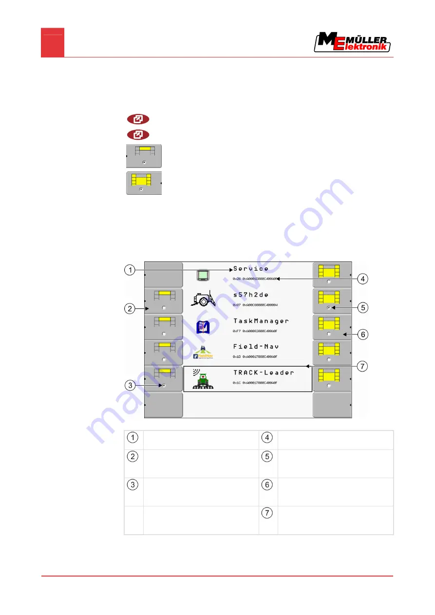
The display is split into the following sections: 
 

  Function icons – left and right 


  Applications section – in the middle, between the function icons. 


Sections in the selection menu 


Name of an application


ISO ID of the application


ISO name of the application 


Function icons on the left


Select an application which will later be 
displayed in the header. 


Selection


The selected application is displayed on the 
main display. 


Selection


The selected application is displayed in the 
header 


Function icons on the right


Open an application on the main display. 


Cursor


Open the selected application using the rotary 
knob. 


Controls 

6.1 

Содержание BASIC-Terminal

Страница 1: ...Installation and operating instructions BASIC Terminal Version 20110308 30322511 02 EN Read and follow these operating instructions Keep these operating instructions in a safe place for later reference ...

Страница 2: ...alid for item number 30322511 30322512 From software version 3 68 Original language German Müller Elektronik GmbH Co KG Franz Kleine Straße 18 33154 Salzkotten Germany Phone 49 0 5258 9834 0 Fax 49 0 5258 9834 90 Email info mueller elektronik de Homepage http www mueller elektronik de Document Copyright ...

Страница 3: ...ofitting 210 4 2 Mounting the terminal in the tractor cab 211 4 2 1 Screwing on the GSM antenna 211 4 2 2 Terminal ports 212 4 3 Connecting the terminal to the basic equipment 212 4 3 1 Checking the ISOBUS compatibility of the basic equipment 213 4 3 2 Selecting the correct basic equipment 213 4 3 3 Connecting the terminal to the basic equipment 214 5 Basic control principles 215 5 1 Getting to gr...

Страница 4: ...the Diagnostics function 236 7 13 1 Jobcomputer diagnostics 237 Sending diagnostic data to the portal 237 7 13 2 CAN Trace settings 237 7 14 Activating an external LightBar 238 7 15 Camera 239 7 15 1 Activating a camera 239 7 15 2 Operating the camera 240 7 16 Configuring FarmPilot 241 7 16 1 Activating FarmPilot 241 7 16 2 Configuring the connection with FarmPilot 242 7 16 3 Entering data in the ...

Страница 5: ...gulations on accident prevention Follow all recognised safety industrial and medical rules as well as all road traffic laws Layout and meaning of warnings All safety instructions found in these Operating Instructions are composed in accordance with the following pattern WARNING This signal word identifies medium risk hazards which could potentially cause death or serious bodily injury if not avoid...

Страница 6: ...and hop growing operations The manufacturer cannot be held responsible for any installation or use of the system that deviates from or exceeds the scope of intended use The manufacturer cannot be held liable for any personal injury or property damage resulting from such improper use All risks involved in engaging in improper usage lie solely with the user Intended use is also understood to include...

Страница 7: ...ons to identify different operating instructions Type of depiction Meaning 1 2 Actions that must be performed in succession Result of the action This will happen when you perform an action Result of an operating instruction This will happen when you have completed all steps Requirements In the event that any requirements have been specified these must be met before an action can be performed Layou...

Страница 8: ... navigation to the field Please call our sales department if you want to unlock this optional software Differences between the two versions of the terminal There are two versions of the terminal BASIC Terminal item no 30322511 BASIC Terminal GSM item no 30322512 You can identify which terminal you have from the ME item number on the nameplate 9 The following table shows the differences in equipmen...

Страница 9: ... you can find all the information you need to definitively identify the product Have these details ready when you contact Customer Services Nameplate on the reverse of the terminal Customer number If the product was manufactured for an agricultural machinery manufacturer the agricultural machinery manufacturer s item number will be shown here Operating voltage The product may only be connected to ...

Страница 10: ...connected to the vehicle s electrical system it is your own responsibility to check whether the installation causes interference with the vehicle s electronic system or other components This applies in particular to the electronic control of EHR front linkage take off shafts engine gear The following requirements must be met in order to retrofit mobile communication systems e g radio phone All far...

Страница 11: ...t the terminal with the bracket installed inside the tractor cab For instance you can use the ME base console for this purpose The base console is not included with the terminal This is included in the delivery content of the ISOBUS basic equipment 13 Base console Screwing on the GSM antenna The GSM antenna transmits information to the FarmPilot portal via a mobile phone network 1 NOTICE There is ...

Страница 12: ...2 Port for analogue camera Only for terminals with a GSM modem installed Item no 30322512 Port A CAN bus port To connect the ISOBUS basic equipment Covering cap for USB port Prevents dust from entering the USB socket Port C Serial port RS232 Connecting the terminal to the basic equipment NOTICE Risk of damage when using non standard basic equipment Connecting the terminal to non standard basic equ...

Страница 13: ...r retrofitting tractors and for signal capture Basic equipment for ISOBUS tractors Item name Basic equipment BASIC Terminal TOP for ISOBUS tractors ISO 11783 with ISOBUS terminal connector Item no 30322541 Suitable for Tractors with a power socket for connecting the ISOBUS basic equipment The power socket must conform to ISO 11783 In this case only one connecting cable is required to link the term...

Страница 14: ...84 1 ISO 11786 Item no 30322560 Equipping the tractor jobcomputer with sensors km h transmission km h radar PTO speed and work position This equipment offers the possibility of fitting the tractor with a front and rear power socket Item no 30322565 Connecting the terminal to the basic equipment 1 Insert the 9 pin cable of the basic equipment into the 9 pin socket A on the terminal 2 Tighten the sa...

Страница 15: ...nd corner of the terminal Control with the rotary knob may vary slightly between the different applications You can use the rotary knob to perform the following actions Turning the rotary knob Move the cursor up and down Change a parameter value Pressing the rotary knob Click on the selected line Activate parameter Confirm input Function keys Operating the function keys is the same across all appl...

Страница 16: ...essing function keys components of the connected machine can be moved or activated As a result people can be injured and property damaged Before pressing a function key Make sure you know what will happen when you press the function key Consult the Operating Instructions of the connected machine or of the agricultural equipment to establish what dangers could arise from pressing that key Fulfill a...

Страница 17: ...ss the function key the function depicted on the function icon will be activated If not function icon appears next to a function key this means that this function key has no function at present Initial start up 1 Installing and connecting the terminal 2 Switch on the terminal 3 Wait for approx 15 seconds until all applications have been loaded 4 Open the Selection menu application The following sc...

Страница 18: ... are loaded when no more progress bars are displayed 6 In the selection menu you can select which application you wish to display next 7 Select the Service line The Service line must be framed by a black square 8 Click on the Service line The following screen will appear You have opened the Service application 9 Configuring the terminal in the Service application 23 Restarting the terminal When re...

Страница 19: ...Basic control principles Restarting the terminal 5 Copyright Müller Elektronik GmbH Co KG 19 2 Wait 30 seconds until the jobcomputers have also been switched off 3 Switch on the terminal ...

Страница 20: ...the application in the main section of the display Display layout in the selection menu The display is split into the following sections Function icons left and right Applications section in the middle between the function icons Sections in the selection menu Name of an application ISO ID of the application ISO name of the application Function icons on the left Select an application which will lat...

Страница 21: ... function keys on the right hand side Display the application shown next to the function icon Both applications will appear on the display Segmentation of the display The display of the terminal BASIC Terminal is split into two sections A different application is diplayed in each section This allows you for example to control the tractor on the field and monitor the field sprayer at the same time ...

Страница 22: ...opyright Müller Elektronik GmbH Co KG In the selection menu you can see which applications can be run with the split display Function icon Function Switch applications in the header section Swap applications between the header section and the main section of the display Controls ...

Страница 23: ...ith the rotary knob Version number Name of the terminal and version of the installed software Function icons section Icons that can be pressed on this screen Controls in the Service application The Service application is controlled using the rotary knob and the function keys Some of the function icons explained here will only appear if a specific function is activated This limits the information s...

Страница 24: ...vated Open the Diagnostics screen Diagnostics is activated Retrieve default values Display DGPS connection status Icons in the Service application You will find the following icons in the Service application Function is activated Function is deactivated Changing the language When you switch on the terminal for the first time the text may appear in a foreign language in German In this chapter you w...

Страница 25: ... foreign language 4 Click on Terminal Einstellungen Display settings 5 Click on Sprache Language 6 Select the abbreviation of your language 7 Press The language in the Service application will be changed 8 Restart terminal The language in other applications will be changed Adjusting the brightness for day or night mode In this chapter you will learn how to adjust the brightness of the display for ...

Страница 26: ...e Activate night mode The brightness of the display will be adjusted immediately Configuring the basic display settings The basic display settings can be adjusted on the Display settings screen 1 Switch to the Display settings screen Service Display settings The following screen will appear 2 Change the desired parameter Parameter Meaning Brightness Day Adjust the brightness for day mode Night Adj...

Страница 27: ...system metric imperial US American user defined Keyboard brightness Set level of keyboard brightness in percent Activating and deactivating applications In the Service application you can activate and deactivate other applications that are installed on the terminal The applications are installed in packages in so called plugins A plugin can contain several applications Name of the plugin Includes ...

Страница 28: ...al purposes for up to 50 hours After this time has elapsed they will be automatically deactivated The amount of free usage time remaining is shown in brackets next to the name of the application To activate a licence you will require an activation number which you will receive on purchasing an application from Müller Elektronik If you request the activation number by phone or by email you will be ...

Страница 29: ...t screen The application is activated You can use the application without any restrictions Deleting files from the USB flash drive NOTICE Potential loss of data Deleted files cannot be retrieved Think very carefully about which file you wish to delete On the File management screen you can delete files from the USB flash drive The File management screen only displays files that are stored in either...

Страница 30: ...eted 5 Delete file red Deleting file Deleting pools You can delete the pools to speed up the terminal s operation Pools are the intermediate storage for the terminal Pools are used to temporarily store graphics or text Over time the pools will become too large and slow down the operation of the terminal After updating the software of a connected jobcomputer If the terminal operates more slowly tha...

Страница 31: ...rminal GPS Receiver When you connect a GPS Receiver to the terminal you must activate and configure it Activating the GPS Receiver In order to activate the GPS Receiver you must first activate its driver A driver is a small program that controls connected farm equipment The drivers for the farm equipment supplied by Müller Elektronik are pre installed on the terminal 1 Switch to the Driver setting...

Страница 32: ...eiver is activated The following function icon will be displayed on the start screen of the Service application You have activated the GPS Receiver Configuring the DGPS Receiver A100 The DGPS Receiver A100 is delivered ready configured However you can change the configuration In this chapter you will learn how to do this You can configure the following parameters in the process Baud rate Setting f...

Страница 33: ...eiver WAAS EGNOS Correction signal in Europe and in North America E DIF Internal calculation of correction data This setting is required outside of the EU and the USA To use e Dif you will require a special version of the DGPS Receiver A100 You can order this this DGPS Receiver from Müller Elektronik with the item number 30302464 Terrain compensation Under this parameter the terrain compensation G...

Страница 34: ...to restart the terminal In these cases the following notification will appear Settings will be adopted after restart You have configured the DGPS Receiver Configuring the GPS TILT Module terrain compensation The GPS TILT Module terrain compensation is connected The driver of the external LightBar is deactivated The external LightBar is not connected 1 Measure the distance between the GPS Receiver ...

Страница 35: ...nges every time the tractor tilts Screenshots A screenshot is a photo of the display If an error occurs when you are using the terminal Customer Services may ask you to capture a screenshot A screenshot can be emailed to Customer Services Email address service mueller elektronik de sent to the FarmPilot portal provided you have activated the FarmPilot portal Configuring the screenshots function Yo...

Страница 36: ...keys briefly in the order depicted While the screenshot is being captured the icon of a photo camera will be displayed in the centre of the display When the camera icon disappears the screenshot has been created You will find the screenshot you captured in the location you specified as the Storage location The USB flash drive saves the screenshots in the folder ScreenCopy Activating the Diagnostic...

Страница 37: ...stomer Services to gather detailed information about your terminal and therefore examine it more thoroughly You have activated the Diagnostics function You have activated the FarmPilot portal 1 Switch to the Jobcomputer diagnosis screen Service Jobcomputer Diagnostics 2 Send diagnostic data The following notification will appear DeviceidentData transfer The data are being uploaded to the portal 3 ...

Страница 38: ... Trace 8 Restart terminal After restarting the terminal CAN Trace will log the communication between the terminal and the jobcomputer 9 Leave the terminal switched on until the set CAN Trace duration has elapsed The CAN Trace function will be deactivated automatically 10 If you specified USB as the storage location verify that the file StartupTrace txt exists on the USB flash drive 11 If this file...

Страница 39: ...trol or TRACK Leader II applications you must also activate the external LightBar in these applications For instructions on how to do so please refer to the operating instructions of these applications Camera Activating a camera If you have connected a camera or camera system to the terminal you must activate it To activate a camera or a camera system you must first activate its driver 1 Switch to...

Страница 40: ...6 You have activated the camera driver Operating the camera Function icon Meaning Switch between several cameras Rotate image Switch fullscreen on and off Save camera settings Exit camera You can press the function keys even if the camera is set to fullscreen mode You have connected and activated the camera 1 Switch to the Camera screen Service The following screen will appear 2 Use the function k...

Страница 41: ...llowing steps Purchase a SIM card and have it activated Activate FarmPilot Enter your FarmPilot access data Refer to the following chapters to learn how to perform these steps Activating FarmPilot To activate FarmPilot on your terminal you must first activate its driver NOTICE High costs from prolonged data transfer If you do not have a flatrate in your mobile phone contract continuous use of Farm...

Страница 42: ... following parameters for the configuration Username Username for FarmPilot Password Password for FarmPilot Provider Opens a screen where the GPRS connection can be configured With most mobile phone providers this configuration occurs automatically If the access data for the GPRS connection differ with your provider you can configure the connection manually You can find precise instructions in the...

Страница 43: ...onfigure parameter Entering data in the FarmPilot access data section Below the characters you will find 5 icons which will assist you when entering the data Delete characters Move cursor to the left Move cursor to the right Confirm and finish input No function 1 Switch to the FarmPilot access data screen Service The following screen will appear 2 Click on the selected line 7 16 3 Controls Procedu...

Страница 44: ...he terminal does not recognise your mobile phone provider Your mobile phone provider has altered the access data for the GPRS connection The values you must enter for the parameters depend on your mobile phone provider You can find out these data from your mobile phone provider You will require the following parameters for the configuration Country Country for which the SIM card is configured Cann...

Страница 45: ...rd Password for the GPRS connection Function icon Function Retrieve default values You can configure the mobile connection as follows You have inserted the SIM card You have activated the FarmPilot portal 1 Switch to the configuration screen for the GPRS connection Provider The following screen will appear 2 Set GPRS connection parameters Controls Procedure ...

Страница 46: ...th a soft damp cloth Only use clear water or glass cleaner Disposing of the unit When it has reached the end of its service life please dispose of this product as electronic scrap in accordance with all applicable EU waste management directives Checking the software version 1 Open the Service application Service 2 The following screen will appear 3 The software version can be found below the ME lo...

Страница 47: ...ipment Typically 0 5 A at 13 8 V Display VGA TFT colour display display size diagonal 14 5 cm resolution 640 x 480 pixels Processor 32 bit ARM920T up to 400 MHz RAM 64 MB SDRAM Boot USB 128 MB Internal clock Buffered by capacitor keeps the time for 2 weeks without an external power supply Keyboard 17 keys plus rotary knob Outputs 2 x CAN 1 x USB 1 x RS232 2 x M12 for two analogue cameras optional ...

Страница 48: ...ectors therefore it is crucial to avoid differences in potential between the pins of these two connectors Pin assignment of port C Port C is an RS232 interface CAUTION Damage to the equipment caused by short circuit Pin 4 of port C is live The voltage depends on the operating voltage of the terminal and is used to supply the DGPS Receiver A100 from Müller Elektronik Other GPS Receivers may suffer ...

Страница 49: ...nt When connected to a 24 V battery the terminal will transfer approx 23 3 V to the connected equipment The use of a GPS Receiver only requires the signals RxD and TxD as well as GND Pin assignment of camera ports 1 and 2 Ports 1 and 2 are used to connect an analogue camera The pin assignment is identical for both ports Ports 1 and 2 are 5 pin A encoded M12 sockets Please refer to the following ta...

Страница 50: ...8 Maintenance and servicing Technical specifications 50 Copyright Müller Elektronik GmbH Co KG Pin Signal 5 Video screen Outer sheathing Screen ...

Страница 51: ...Notes 9 Copyright Müller Elektronik GmbH Co KG 51 Notes 9 ...

Отзывы: