


MTX-GTW
www.mtxm2m.com
www.matrix.es
2015/08 v1.6
Page
18
/
44
MTX Terminals® by MATRIX ELECTRONICA S.L.U
5.3
User Interfaces
5.3.1
Status LED
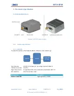
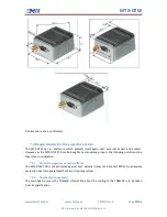
The MTX-GTW has four LEDs to inform the user about different status conditions. The following table
shows the different LED indications.
Led
Status remark
DLp1
Power Supply OK. (Green LED )
DL1
Free for user information. Connected to GPIO3_6. (Red LED)
DL2
Ethernet link speed LED indication. On with 100Mbps, OFF with 10Mbps. (Red LED)
DL3
Ethernet link activity LED indication. (Green LED)
Both DLp1 and DL1 are visible though the LED window placed on the top of the MTX-GTW box.
5.3.2
DIP Switch
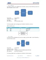
The MTX-GTW has one Dip-Switch with configuration purposes. The following table shows
information about the signals connected to the Dip Switch.
SW1:
Pin
Signal
Remark
1
LCD_D03
Recovery Switch (Default OFF= Normal Boot)
2
LCD_D00
Recovery Switch (Default OFF= Normal Boot)
3
SW1_3
Connected to RS485/RS232#. (Default OFF=RS232)
4
SW1_4
Connected to Half_Duplex/Full_Duplex#. (Default OFF = Full-Duplex)
5
VCC_OUT (3V3)
VCC_OUT (DB15_PIN10). ON = 3,3VDC
6
VCC_OUT (5V)
VCC_OUT (DB15_PIN10). ON = 5VDC
7
USB_OTG_ID
USB OTG Identification. (OFF=OTG, ON=Only Host)
8
GPIO_6
Input signal for User information. Connected to GPIO0_24


