TempoLink Smart Assistant
Operation Manual
I
6
I
AS00 (sensor – cable)*
USB cable for optional connection of TempoLink smart
assistant to a computer
The TempoLink smart assistant can be connected to all
sensors of the R-Series
V
family. Depending on the sensor
output, different adapter cables are available to connect the
TempoLink smart assistant to the R-Series
V
sensor. Use the
appropriate adapter cable for the sensor output. Connect
the barrel connector of the adapter cable to the connection
point labeled “OUTPUT SENSOR” on the TempoLink smart
assistant. Next, connect the opposite end of the adapter cable
to the power supply at the R-Series
V
sensor. The TempoLink
smart assistant also provides the supply power for the sensor.
Fig. 3 shows one possible version as an example. The adapter
cable is available in different versions depending on the sensor
output. See the specific R-Series
V
operation manual for more
information.
If the sensor is connected to another power supply
disconnect the power supply before connecting TempoLink
smart assistant to the sensor.
NOTICE
When disconnecting the power supply of the sensor
possibly error messages occur at the connected controller.
Do not exceed the maximum cable length between
TempoLink smart assiant and R-Series
V
sensor of 30 m.
OUTPUT
INPUT
SENSOR
24V D
C
5. Connection of TempoLink smart assistant to
R-Series
V
sensor
OUTPUT
INPUT
SENSOR
24V D
C
OUTPUT
INPUT
SENSOR
24V D
C
6. Connection of TempoLink smart assistant to power
supply
There are two ways:
6.1 Using the plug-in power supply with plug adapters
Connect the barrel connector to the “INPUT 24 VDC” port
on the TempoLink smart assistant. Next, insert the plug into
the outlet. Additional outlet adapters are supplied to support
regional requirements.
6.2 Using the cable for insertion in an existing sensor
power supply with sensor mating connector and barrel
connector (only R-Series
V
EtherNet/IP™, EtherCAT
®
,
POWERLINK and PROFINET)
Connect the supplied sensor mating connector to your
existing power supply connector that was removed from the
sensor. Connect the barrel connector to the “INPUT 24 VDC”
port on the TempoLink smart assistant. Fig. 5 shows one
possible version as an example. The adapter cable is available
in different versions depending on the sensor output. See the
specific R-Series
V
operation manual for more information.
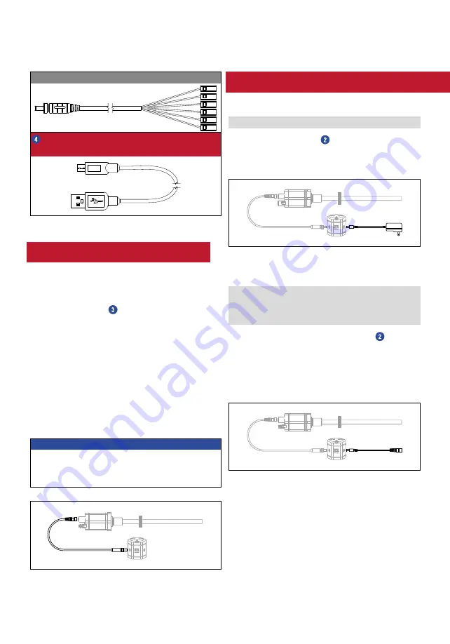
Fig. 2: Package content of the TempoLink kit, part 2
Fig. 3: Connection of TempoLink smart assistant to R-Series
V
sensor
Fig. 4: Connection of TempoLink smart assistant with the plug-in
power supply
Fig. 5: Connection of TempoLink smart assistant with the cable for
insertion in an existing sensor power supply cable for R-Series
V
EtherNet/IP™, EtherCAT
®
, POWERLINK and PROFINET


