MTS Sensors
M-Series Model MG Digital Gauge, Transmitter Electronics - Replacement Guide 551104 A
Transmitter electronics replacement procedure
3
Removing the transmitter electronics boards
Complete the following steps to remove and replace your transmitter
electronics board after you have successfully created a data restore
file.
Caution:
Ensure that all power is disconnected and that all lockout procedure(s) are
followed prior to opening the transmitter instrument housing.
Remove any dirt, debris, or liquid from the top of the instrument
1.
enclosure.
Remove the instrument housing cover.
2.
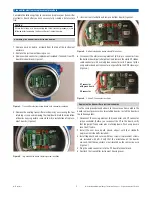
Remove wired connector (replacement included if needed) from PC
3.
board terminal block (
Figure 3
).
Remove the existing transmitter electronics by unscrewing the four
4.
retaining screws and removing the (top) board. Note the orientation
of boards housing before removal to aid in installation of replace-
ment boards (
Figure 4
).
Transmitter electronics top board with connector removed
Figure 3.
Top electronics board retaining screw locations
Figure 4.
Unscrew four standoffs and remove bottom board (
5.
Figure 5
).
Disconnect the white sensing element (SE) 6-pin connector from
6.
the bottom board (pull straight out) and remove the white DT ribbon
cable connector with a small green connector card if present (slide
wing outward and pull connector out parallel to the PCB sideways)
(
Figure 6
).
SE and DT connector locations
Figure 6.
Use the same procedure and adhere to the same cautions noted in the
board removal process when reinstalling boards. Install the boards in
the following order:
Reconnect the sensing element (SE) connector and DT connector
1.
(when available). Before you reconnect the DT to the board, verify
that the gold DT connector pins are facing down. Push wing back in
lock the DT cable.
Install the new base board (round edges) with four standoffs
2.
(replacement standoffs included).
Install top board and secure with four screws (replacement screws
3.
are included with kit). Verify that the orientation of the boards
are such that the connectors are all located on the same side as in
(
Figure 4)
.
Plug the wired connector into the PC board terminal block.
4.
Reattach the transmitter instrument housing cover.
5.
Replacing the transmitter electronics boards
DT connector
with green board
SE connector
Bottom electronics board standoffs locations
Figure 5.


