830-860 SERIES SELF-PROPELLED MOWERS
15
5.
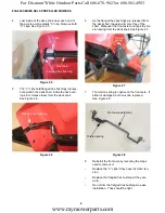
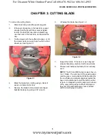
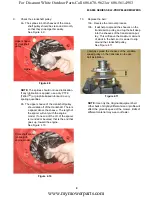
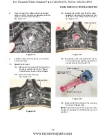
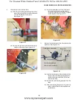
Pull the cable and spring through the opening in
the deck. See Figure 5.19.
6.
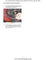
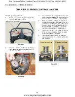
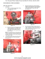
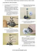
Remove the push-barb fasteners that hold the
control panel to the upper handlebar.
See Figure 5.20.
Figure 5.19
Pull clutch cable up
Figure 5.20
Push-barb
fastener
Clutch bale
bracket
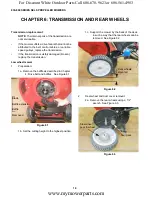
7.
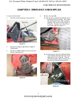
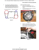
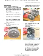
Pry the cable bracket loose from the upper han-
dlebar. See Figure 5.21.
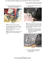
8.
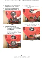
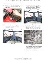
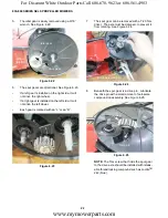
With the cable slack, the Z-fitting at the top end
of the cable core can be un-hooked from the
clutch bale. See Figure 5.22.
NOTE:
Depending on parts availability, the cable
may have to be replaced in tandem with the
engine stop cable.
9.
Install the replacement cable by reversing the
removal process.
Figure 5.21
Cable
bracket
Figure 5.22
Engine stop cable
Clutch cable
www.mymowerparts.com
For Discount White Outdoor Parts Call 606-678-9623 or 606-561-4983

