830-860 SERIES SELF-PROPELLED MOWERS
22
5.
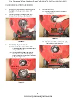
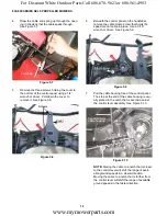
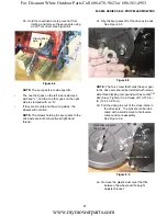
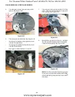
The idler gear is easily removed using a 9/16”
wrench. See Figure 6.22.
6.
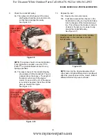
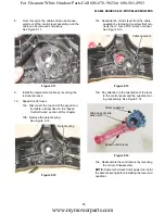
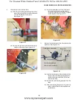
The spur gears are directional. See Figure 6.23.
•
If a left gear is installed on the right side, it will
not drive the right wheel.
•
If a right gear is installed on the left side, it will
not drive the left wheel.
•
Each gear is marked with an “L” or an “R”.
7.
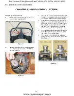
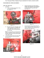
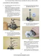
The spur gear can be removed with a T-20 Torx
driver. The axle must be clamped, to prevent it
from rotating. See Figure 6.24.
8.
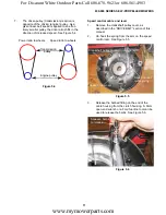
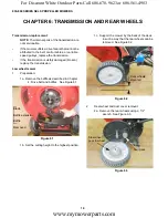
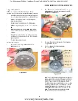
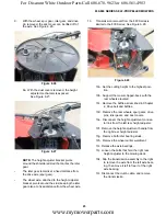
Beneath the spur gear is a drive pin. Lubricate
the drive pin with a small amount of anti-seize
compound on assembly. See Figure 6.25.
NOTE:
The Torx screw that holds the spur gear
to the drive axle should be installed with releas-
able thread locking compound such as Loctite
TM
242 (blue).
Figure 6.22
Idler gear
Spur gear
Wheel
rotation
Figure 6.23
“L”
Figure 6.24
Drive axle clamped
Figure 6.25
Drive pin
Spur gear
www.mymowerparts.com
For Discount White Outdoor Parts Call 606-678-9623 or 606-561-4983

