830-860 SERIES SELF-PROPELLED MOWERS
13
8.
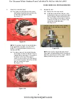
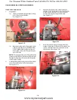
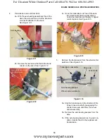
From this point, the cable-end can be maneu-
vered out of the control lever assembly, and the
cable can be removed completely.
See Figure 5.11.
9.
Install the replacement cable by reversing the
removal process.
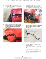
10.
Speed Control lever:
10a. Disconnect the top end of the speed con-
trol cable, as described in the “Speed
Control Cable” section of this chapter.
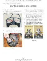
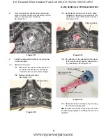
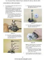
10b. Remove the detent spring:
See Figure 5.12.
Figure 5.11
Detent spring
Figure 5.12
Detent spring
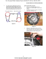
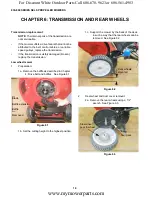
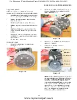
10c. Separate the control lever from the cable
quadrant by removing the screw that con-
nects them. Use a 5/16” wrench or driver.
See Figure 5.13.
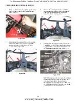
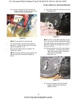
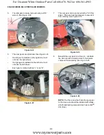
10d. Pay attention to the orientation of the lever
to the control panel and the quadrant dur-
ing reassembly. See Figure 5.14.
10e. Reassemble the control panel by reversing
the order of disassembly.
NOTE:
Some technicians find it easier too instal
the detente spring before installing the lever and
quadrant.
Figure 5.13
Cable quadrant
Figure 5.14
Speed control lever
Cable quadrant
Wide boss fits into
wide notch
www.mymowerparts.com
For Discount White Outdoor Parts Call 606-678-9623 or 606-561-4983


