


QM7500 Technical Manual
QM31930/03093 Rev AD
Servicing 19
Replacing the Circuit Board
Removing the Circuit Board
1) Prepare your QM7500 for servicing. (See page 6.)
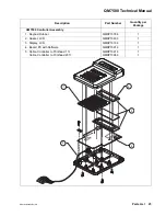
2) Remove the controller from the controller mounting frame.
3) Remove the three screws from the controller bottom to remove the controller
top.
Note: Avoid handling the new circuit board as much as possible;
repeated handling could damage it.
4) Using pliers, carefully pull out the wires from the barrel terminals one at a
time.
5) Remove the old circuit board.
6) Remove the display from the old circuit board, disconnecting the connector.
7) Remove the PROM if necessary, by carefully prying it out. Be careful not to
bend the legs. Make note of the direction of the notch on the PROM. This
notch must match up to the notch on the socket on the new circuit board.
Installing the New Circuit Board
1) Insert the PROM into its connector on the new circuit board. Match up the
notch on the PROM with the notch on the socket to make sure the PROM is
pointing in the proper direction.
2) Replace the display in the new circuit board.
3) Place the new circuit board in the top half of the controller.
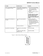
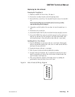
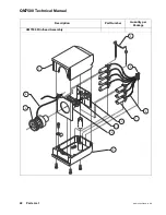
4) Reconnect the barrel terminals. Next to each barrel terminal on the circuit
board, is printed the color code of the wire that must be installed into that
specific terminal. (See Figure D.)
5) If necessary, adjust the intensity of the display screen by adjusting the
potentiometer on the back side of the circuit board.
Figure D: Barrel Terminal Wiring Diagram
light brown
pink
brown
white
red
yellow
purple
gray
green
orange
blue
black


