


QM7500 Technical Manual
QM31930/03093 Rev AD
Servicing 13
2) Remove the printhead cover by removing the three screws from the bottom of
the printhead. With the unit flat on the workbench, place your thumb on the
regulator and press down lightly as you lift up the top half of the printhead.
Note: Hold the components in place with your finger if necessary. Make
sure the valve/photocell board assembly remains in the printhead base.
Also, avoid unnecessary flexing of the cable between the two boards to
prevent damaging the cable connections.
3) Slide out the photocell board.
4) Locate the defective valve. (If a valve has shorted, it will usually be locked
open with ink leaking. A good valve has a resistance reading of approximately
16 ohms.)
5) Remove the valve retaining clip.
6) If necessary move aside functioning valves to get to the defective valve.
7) Disconnect both pieces of tubing from the valve.
CAUTION: Remaining ink pressure may cause ink to shoot out of the
tubing.
8) Disconnect the old valve from the valve board.
Installing the New Valve
1) Connect the tubing from the ink manifold to the intake (off-center) port on the
new valve.
2) Connect the tubing from the nozzle to the outlet (center) port on the new
valve.
3) Plug the new valve into the valve board.
4) Replace the valve retaining clip.
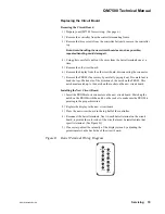
5) Slide the photocell board back into place, photocells facing out.
6) Replace the printhead cover, remount, and purge for several minutes.
Replacing the Regulator
Removing the Regulator
1) Prepare your QM7500 for servicing. (See page 6.)
2) Remove the printhead cover by removing the three screws from the bottom of
the printhead. With the unit flat on the workbench, place your thumb on the
regulator and press down lightly as you lift up the top half of the printhead.
Note: Hold the components in place with your finger if necessary. Make
sure the valve/photocell board assembly remains in the printhead base.
Avoid unnecessary flexing of the cable between the two boards to
prevent damaging the cable connections.
3) Carefully lift the controller mounting frame off the bottom half of the
printhead.
4) Carefully pull the tubing off the regulator ports.


