English
Operation manual
17
a b
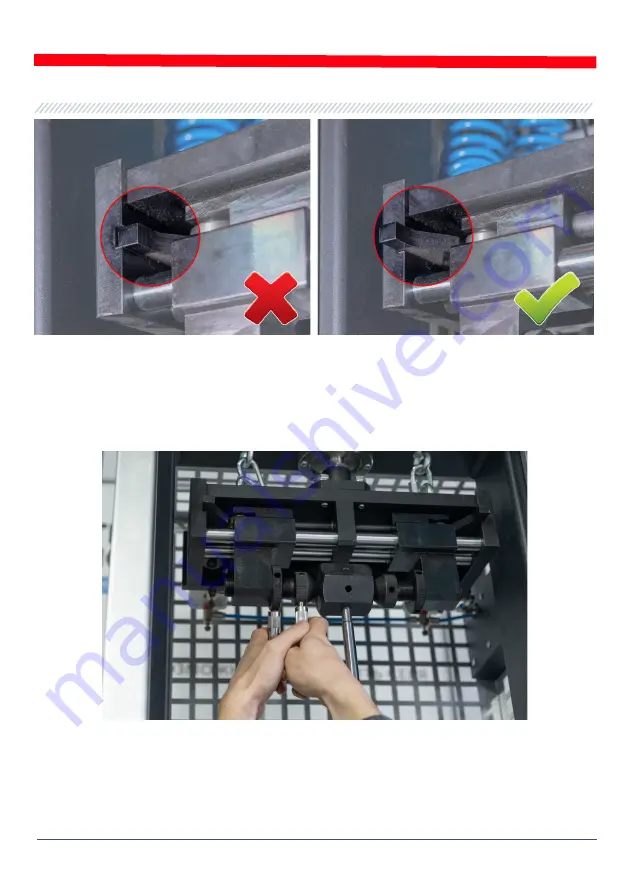
Figure 17. Position of the pneumatic clip cams in the «clamp» state
a - not right; b - right.
3.3. Additionally, tighten the pushers to the shock absorber mount (prism), and then tighten the
lock nuts pos.4 fig.4 (see fig.18).
Figure 18. Tightening of the locking nuts in the clamp
4. Install and fix the shock absorber in the lower clamp, for this:
4.1. Loosen the stopper of the lower clamp by turning the lever pos.4 fig. 2 counterclockwise by 2
turns (see fig. 19).


