6
INSTALLATION INSTRUCTIONS
M S D
• W W W . M S D P E R F O R M A N C E . C O M • ( 9 1 5 ) 8 5 7 - 5 2 0 0 • F A X ( 9 1 5 ) 8 5 7 - 3 3 4 4
TIMING
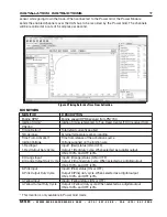
This plot controls the amount of timing retard applied to the engine as a function of “Time From
Activation”.
Note:
This timing is only available in Power Grid Mode (i.e. when the Power module is connected to
a Power Grid PN7730).
DATA ACQUISITION
The data acquisition system works in conjunction with the Power Grid (PN7730) data recorder. It allows
the user to record input activations as well as the state of any of the outputs and temperature
Figure 4 Output Duty Cycle vs Time From Activation.
Figure 3 Settings.
The 'Temperature Setting' and
'AC Input' features will be enabled
when 'ON/OFF' or 'PWM' are
selected.
The 'Timer During Wiring Disable'
setting will show when 'Launch' is
selected


