INSTALLATION INSTRUCTIONS 5
M S D
• W W W . M S D P E R F O R M A N C E . C O M • ( 9 1 5 ) 8 5 7 - 5 2 0 0 • F A X ( 9 1 5 ) 8 5 7 - 3 3 4 4
disabled by one of the wires. This setting is available only if “Launch” is selected as the
”Wire
Activation Source 1”
. The timer of every output will reset to 0 during launch mode if “Launch”
is used as a condition for activation.
Possible options:
Continue:
Timer will continue to increment even when the output is disabled due to
one of the wires.
Pause:
Timer will pause, or “freeze”, when the output is disabled due to one of the wires.
Restart:
Timer will clear, or become 0, when the output is disabled due to one of the
wires.
Note:
Launch mode can be selected as the activation source only in "Wire Activation Source 1" and
if the Power Module is in Power Grid Mode.
Time Setting:
Determines if the output will be controlled directly by the “Activation Source” or by the
“Time from Activation”.
Possible options:
ON/OFF:
The output relay is directly controlled by the activation wires.
Time Setting:
The output will become active (ON) when the time from activation
exceeds the
“Activation Time”
value and will stay active for the number of seconds
specified in the
“Activation Duration”
setting.
Note:
Activation Duration value of '0'
means: indefinite.
Graph:
The output will activate at a duty cycle set in the corresponding graph.
RPM Setting:
Enables or disables the use of Engine Speed (RPM) as a condition for activating the
output. The “RPM Setting” is available only in Power Grid mode.
Activation:
Allows the output to become active only when the Engine Speed exceeds this setting.
Deactivation:
When set above the “Activation” speed, the output will deactivate when the engine
speed is above the “Deactivation” speed (Window control). Alternatively, when the
“Deactivation” is set below the “Activation”, the output will deactivate when the engine speed
drops below the “Deactivation” speed (Hysteresis).
Note:
Each output within the Power Module can activate engine timing retard similar to the step retard
within the Power Grid. Therefore, with the use of the Power Module there are effectively, up
to four additional Step Retard inputs. The retard functionality timers are tied to the status of
the solid state relay.
Total Retard:
The maximum ignition timing to be removed from the engine when the output is activated.
Minimum Engine RPM:
The minimum engine speed that must be met to enable the total retard.
Note:
The timing retard here is controlled by the state of the output relay
ON Ramp Time:
The time it takes to reach the full “Total Retard”. For example, with 10 degrees
of “Total Retard” and 1 second “Ramp Time”, the controller will retard 1 degree every 0.1
seconds until the full 10 degrees of timing has been pulled out. This timer will start only after
the “Minimum Engine RPM” condition is achieved.
OFF Delay:
The time the “Total Retard” remains in effect after the output turns completely OFF (or
0% duty cycle).
OFF Ramp Time:
The time it takes to decay the “Total Retard”, ramping timing back into the motor
RPM Setting:
This setting enables/disables the ability to control the output as a function of engine
speed (RPM).
Activation:
The output activates when the engine speed exceeds this value.
Deactivation:
When set above the “Activation” speed, the output will deactivate when the
engine speed is above the “Deactivation” speed. On the other hand, when the “Deactivation”
is set below the “Activation”, the output will deactivate when the engine speed drops below
the “Deactivation” speed.
Note:
“Total Retard” and “RPM Setting” are only available in Power Grid Mode (i.e. when the Power
module is connected to a Power Grid PN7730).
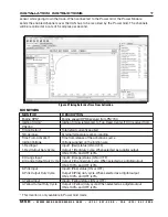
DUTY CYCLE
This plot controls the output duty cycle as a function of “Time From Activation”.
Note:
This plot is
functional only when the “Time Setting” is set to “Graph”.


