


ID20
Industrial Door Microwave Motion Sensor
INSTALLATION INSTRUCTIONS
Page 4
(/MANU) ID20v0913
8701 Castle Park Drive
Indianapolis, Indiana 46256
Telephone: (317) 842-2545
www.mssedco.com
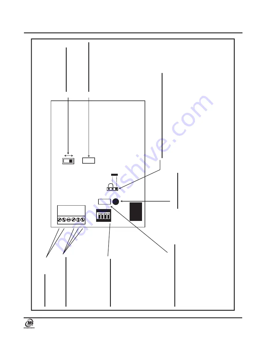
FIGURE 2
1
2
3
4
5
6
Input P
ow
er
12 t
o 2
4 V
olts A
C/DC
1 2 3 4
ON
1 2 3
RELA
Y
Direction
App
Dpt
Op
tion Dip Switc
h
#1 Switch F
unction:
OFF = cy
cle rela
y upon po
w
er up.
ON = no cy
cle rela
y upon po
w
er up.
#2 Switch F
unction:
Speed Det
ection Adjus
tment
ON (def
ault) = 3 m
ph+
OFF = 1 m
ph+
#3, & #4 = no function
R
ela
y Connections
4 = Normally Open (N.O.) 5 = Common 6 = Normally Closed (N.C.)
NO
TE:
R
ela
y is with po
w
er applied and
unit se
tup f
or F
ailsaf
e operation.
Time Dela
y Adjus
tment
0 t
o 5 seconds
Clockwise t
o increase, count
er
clockwise
to decrease.
NO
TES:
1) The LED Indicat
or is illuminat
ed whene
ver the R
ela
y is activ
at
ed.
2) The Range A
djustment allo
ws the P
att
ern/Distance t
o be v
aried f
or each individual installation.
3) The Time Dela
y A
djustment se
ts the rela
y hold time af
ter the unit has st
opped de
tecting mo
tion.
R
ela
y F
ailsaf
e Selection Jumper
Jum
per 1&2 = F
ailsaf
e operation
Jum
per 2&3 = F
ail Secure operation
Direction Switc
h
(Appr
oach or Depar
t)
Range Adjus
tment
Variable Contr
ol -
Appr
ox. 0 t
o 60 F
ee
t
LED Indicat
or