Aufbau- und Montageanleitung IV
IV
IV
IV
IV-11/15
-11/15
-11/15
-11/15
-11/15 VFD Uhr „J
VFD Uhr „J
VFD Uhr „J
VFD Uhr „J
VFD Uhr „Jenn
enn
enn
enn
enny r
y r
y r
y r
y reloaded“
eloaded“
eloaded“
eloaded“
eloaded“
Assembly- and Mounting-Instructions IV
IV
IV
IV
IV-11/15
-11/15
-11/15
-11/15
-11/15 VFD Cloc
VFD Cloc
VFD Cloc
VFD Cloc
VFD Clock „J
k „J
k „J
k „J
k „Jenn
enn
enn
enn
enny r
y r
y r
y r
y reloaded“
eloaded“
eloaded“
eloaded“
eloaded“
– 2 –
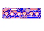
Wir beginnen mit dem Bestücken der Bauteile mit niedriger Bauhöhe. S tarten Sie mit den
Widerständen und hier am besten mit denjenigen, die am meisten in der Schaltung vor-
kommen. Bestücken Sie immer zuerst einen Wert komplett, bevor Sie den nächsten
Widerstandswert nehmen. R15 und R17 werden verikal eingesetzt und jetzt noch nicht
bestückt!
Bestücken Sie jetzt auch nicht R14.
Beachten Sie auch die beiden Induktivitäten
L2 und L3, dass Sie diese nicht mit den 1 kOhm Widerständen verwechseln. Seien Sie
auch vorsichtig beim Abbiegen der Anschlussbeine des Quarzes. Bestücken Sie dann die
beiden Dioden und achten Sie auf die Lage des weißen Rings. Die „Polung“ der sechs
Arrays RN1...6, ist unbedeutend. Danach bestücken Sie die USB-Buchse (Tipp: Fixieren
Sie die Buchse, indem Sie einen Pin am Gehäuse von der Bauteileseite aus anlöten). Als
nächstes werden alle Keramik-Kondensatoren bestückt und anschließend die beiden läng-
lichen IC-Fassungen. Achten Sie hier besonders auf die Lage der Nase in den Fassungen.
We will start with the low profile electronic parts; so let’s start with the resistors and here it
is best to start with those values which are mostly commonly used in the circuit. First finish
assembling one value before you pick up the next. R15 and R17 are mounted upright and
may not assembled at this stage!
Do also not fit R14 yet.
Please do also not mismatch both
inductors L2 and L3 with the 1 kohms resistors.
Please be also carefully when beding the crystal’s leads. Next is to assemble both diodes.
Note the polarity which is marked with a white ring on the diodes package.
The “polarity” of the six resistor arrays RN1...6, which are assembled next, is negligable.
Next step is to assemble the USB jack (Tip: Solder one of the case’s pads from the component
side to fix the part).
Following assemble all ceramic cap acitors and than both oblong IC-socket s. Take special
care for the notches at the sockets.
STOP
Ein paar Worte zur verwendeten Leiterplatte
Dies ist eine sog. 4-Lagen Leiterplatte. Das bedeutet, dass sich Leiterbahnen nicht
wie üblich nur auf der Bauteile- und Lötseite befinden, sondern auch noch „inner-
halb“ in der Leiterplatte auf zwei zusätzlichen Lagen. Sie werden dies beim Löten
bemerken, dass Sie ein wenig mehr Zeit benötigen, bis das Lötzinn sauber fließt.
Im Umkehrschluss bedeutet dies, dass Sie mit einer mechanischen Lötpumpe
oder Entlötlitze die Bauteile NICHT MEHR auslöten können ohne das Board zu
zerstören. Falls Sie einen Bestückungsfehler gemacht haben, lesen Sie bitte unbe-
dingt die Tipps zum Auslöten auf der letzten Seite.
Some words about the printed circuit board
This is a so-called 4-layer PCB, which means that copper tracks are not only present
on the component and solder site, but also the "inside" of the printed circuit board on
two additional inner layers. You will notice this when soldering as you'll need a little
bit more time until the solder flows.
On the other hand, this means also that you CANNOT DESOLDER components with
a mechanical de-soldering pump or soldering wick without screwing up the board.
If you have made an assembly fault, please read the tips for de-soldering on the last
page of this assembly manual.
!
4n7
!
100n
Nase / Notch
Nase / Notch
Hier zuerst anlöten / Solder here first
Induktivitäten / Inductors
Ring
Ring
R14 hier nicht bestücken
Do not fit R14 on this position


