


PAGE 36 — DCA-150SSJU — PARTS AND OPERATION MANUAL — REV. #3 (09/07/01)
E
L
B
A
L
I
A
V
A
S
E
G
A
T
L
O
V
.
8
E
L
B
A
T
E
G
A
T
L
O
V
E
S
A
H
P
3
)
E
L
B
A
H
C
T
I
W
S
(
T
L
O
V
8
0
2
T
L
O
V
0
2
2
T
L
O
V
0
4
2
T
L
O
V
6
1
4
T
L
O
V
0
4
4
T
L
O
V
0
8
4
E
S
A
H
P
E
L
G
N
I
S
)
E
L
B
A
H
C
T
I
W
S
(
T
L
O
V
0
2
1
T
L
O
V
7
2
1
T
L
O
V
9
3
1
T
L
O
V
0
4
2
T
L
O
V
4
5
2
T
L
O
V
7
7
2
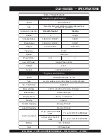
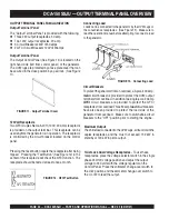
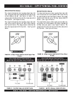
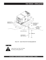
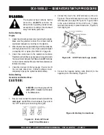
Output Terminal Panel Available Voltages
A wide range of voltages are available to supply load to
many different applications. Voltages may be selected by
using the voltage selector switch and how you hookup
your hard wire connection to the generator. To obtain some
of the voltages listed, fine adjustment with the Voltage
Regulator on the control panel is necessary. See the table
below (Table 8) for a list of available voltages the generator
is able to supply.
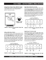
Voltage Selector Switch
The voltage selector switch is located above the UVWO
Hard Wire Hookup Panel. It has been provided for ease of
voltage selection.
CAUTION :
NEVER
switch Voltage Selector Switch
position while the engine is engaged.
Voltage Selector Switch Locking Button
The voltage selector switch has a locking button to protect
the generator and generator load from being switched while
the engine is running. To lock the Voltage Selector Switch,
press in the red button located on the Voltage Selector
Switch, and use a pad lock to hold it into this position.
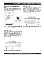
Over Current Relay
An over current relay is connected to the circuit breaker.
In an over current situation, both the circuit breaker and
the over current relay may trip. If the circuit breaker can
not be reset, the reset button on the over current relay
must be pressed. The over current relay is located in the
control box.
s
p
m
A
m
u
m
i
x
a
M
.
9
e
l
b
a
T
:
l
e
d
o
M
U
J
S
S
0
5
1
A
C
D
d
e
t
a
R
e
g
a
t
l
o
V
s
p
m
A
m
u
m
i
x
a
M
e
s
a
h
P
e
l
g
n
i
S
t
l
o
V
0
2
1
)
e
r
i
w
4
(
s
p
m
a
3
.
3
3
3
e
s
a
h
P
e
l
g
n
i
S
t
l
o
V
0
4
2
)
e
r
i
w
4
(
s
p
m
a
7
.
6
6
1
e
s
a
h
P
e
e
r
h
T
t
l
o
V
0
4
2
s
p
m
a
1
6
3
e
s
a
h
P
e
e
r
h
T
t
l
o
V
0
8
4
s
p
m
a
0
8
1
e
s
U
e
l
c
a
t
p
e
c
e
R
.
0
1
e
l
b
a
T
e
s
U
n
i
r
e
w
o
P
e
l
c
a
t
p
e
c
e
R
r
e
w
o
P
e
l
b
a
l
i
a
v
A
V
0
8
4
/
0
4
2
e
s
a
h
P
-
3
V
0
2
1
/
0
4
2
e
s
a
h
P
e
l
g
n
i
S
t
s
i
w
T
r
o
9
6
3
6
S
C
k
c
o
L
I
C
F
G
x
e
l
p
u
D
A
M
E
N
V
0
2
1
R
0
2
-
5
A
V
K
W
K
W
K
0
5
1
7
8
0
6
4
1
8
.
5
8
2
.
1
2
4
1
6
.
4
8
4
.
2
8
3
1
4
.
3
8
6
.
3
3
3
1
2
.
2
8
8
.
4
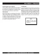
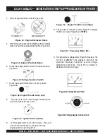
Maximum Amps
The following table show the maximum amps the entire
generator can provide. Do not exceed the maximum amps
listed. (See Table 9)
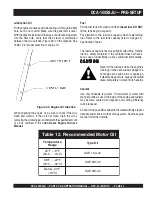
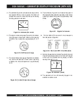
Receptacle Use
When the UVWO terminals are providing power, the
receptacle power available decrease. Do not exceed
receptacle power available listed on Table 10.
DCA-150SSJU — OUTPUT TERMINAL PANEL OVERVIEW
Содержание DCA-150SSJU
Страница 2: ...PAGE 2 DCA 150SSJU PARTS AND OPERATION MANUAL REV 3 09 07 01 ...
Страница 22: ...PAGE 22 DCA 150SSJU PARTS AND OPERATION MANUAL REV 3 09 07 01 DCA 150SSJU GENERATOR DECALS ...
Страница 25: ...DCA 150SSJU PARTS AND OPERATION MANUAL REV 3 09 07 01 PAGE 25 NOTE PAGE ...
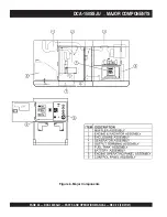
Страница 27: ...DCA 150SSJU PARTS AND OPERATION MANUAL REV 3 09 07 01 PAGE 27 DCA 150SSJU DIMENSIONS Figure 7 Dimensions ...
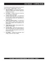
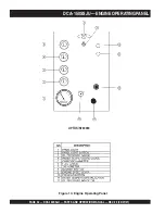
Страница 28: ...PAGE 28 DCA 150SSJU PARTS AND OPERATION MANUAL REV 3 09 07 01 DCA 150SSJU CONTROL PANEL Figure 8 Control Panel ...
Страница 61: ...DCA 150SSJU PARTS AND OPERATION MANUAL REV 3 09 07 01 PAGE 61 DCA 150SSJU WIRING DIAGRAM GENERATOR ...
Страница 63: ...DCA 150SSJU PARTS AND OPERATION MANUAL REV 3 09 07 01 PAGE 63 DCA 150SSJU WIRING DIAGRAM ENGINEWITH CONTROLLER ...
Страница 66: ...PAGE 66 DCA 150SSJU PARTS AND OPERATION MANUAL REV 3 09 07 01 GENERATOR ASSY DCA 150SSJU GENERATOR ASSY ...
Страница 68: ...PAGE 68 DCA 150SSJU PARTS AND OPERATION MANUAL REV 3 09 07 01 DCA 150SSJU CONTROL BOX ASSY CONTROL BOX ASSY ...
Страница 70: ...PAGE 70 DCA 150SSJU PARTS AND OPERATION MANUAL REV 3 09 07 01 DCA 150SSJU CONTROL BOX ASSY CONTROL BOX ASSY ...
Страница 84: ...PAGE 84 DCA 150SSJU PARTS AND OPERATION MANUAL REV 3 09 07 01 BATTERY ASSY DCA 150SSJU BATTERY ASSY ...
Страница 86: ...PAGE 86 DCA 150SSJU PARTS AND OPERATION MANUAL REV 3 09 07 01 MUFFLER ASSY DCA 150SSJU MUFFLER ASSY ...
Страница 88: ...PAGE 88 DCA 150SSJU PARTS AND OPERATION MANUAL REV 3 09 07 01 FUEL TANK ASSY DCA 150SSJU FUELTANK ASSY ...
Страница 94: ...PAGE 94 DCA 150SSJU PARTS AND OPERATION MANUAL REV 3 09 07 01 RUBBER SEALS ASSY DCA 150SSJU RUBBER SEAL ASSY ...
Страница 99: ...DCA 150SSJU PARTS AND OPERATION MANUAL REV 3 09 07 01 PAGE 99 NOTE PAGE ...


