

- 11 -
STEP 1:
Plug your power cord’s M23 connector to the power input port of the
TN-5510 switch.
STEP 2:
Screw the nut on your power cord connector to the power input connector
on the switch to ensure a tight connection.
ATTENTION
Before connecting the TN-5510 to the power input, make sure the
power source voltage is stable.
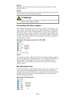
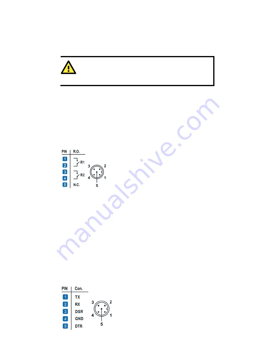
Connecting the Relay Outputs
Each TN-5510 switch has two sets of relay outputs—relay output 1 and
relay output 2. The M12 A-coded 5-pin male connector on the TN-5510’s
front panel is used for the two relay outputs. Use a power cord with an
M12 A-coded 5-pin female connector to connect the relay contacts from
the switch. You may purchase an M12 power cable from Moxa. The model
number of the cable, which must be purchased separately, is CBL-M12
(FF5P)/OPEN-100 IP67.
Pinouts for the relay output port on TN-5510.
N.C.: Not connected
FAULT:
The two sets of relay contacts of the M12 A-coded 5-pin male connector
are used to detect user-configured events. The two wires attached to the
fault contacts form an open circuit when a user-configured event is
triggered. If a user-configured event does not occur, the fault circuit
remains closed.
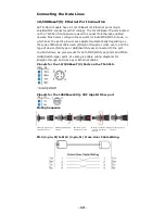
RS-232 Connection
The TN switch has one RS-232 (M12 5pin) console port, located on the
front panel. Use M12 to DB9 console cable to connect the TN switch
console port to your PC's COM port. you may than use a console terminal
program, such as Moxa PComm Terminal Emulator to access the TN
switch's configuration utility.
M12 Console Port Pinouts


