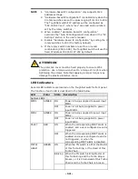
Moxa Technologies ToughNet TN-5510-2GLSX-ODC Скачать руководство пользователя страница 10


- 10 - 


ATTENTION 

This product is intended to be mounted to a well-grounded 

mounting surface such as a metal panel. 

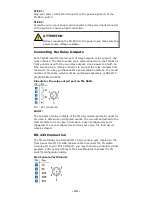
Connecting the Power Supplies 

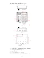
The ToughNet TN-5510 switches support two sets of power 
supplies—power input 1 and power input 2.The M23 6-pin male connector 
on the TN-5510’s front panel is used for the dual power inputs. Use a 
power cord with an M23 6-pin female connector to connect the power 
inputs to the switch. 

Pinouts for the power input port on the TN-5510 


Pinouts for the power input port on the TN-5510. 
Pin 

Description 

Usage 

PWR1 Live / DC + 

Connect “PWR1 Live / DC +” to the Live 
terminal when using an AC power source 
or to the positive (+) terminal when using 
a DC power source. 

PWR1 Neutral / DC -  Connect “PWR1 Neutral / DC –“to the 

Neutral terminal when using an AC power 
source or to the negative (-) terminal 
when using a DC power source. 

Chassis Ground 

Connect the “Chassis Ground” to the 
safety ground terminal for AC inputs or to 
the equipment ground bus for DC inputs. 

PWR2 Neutral / DC -  Connect “PWR2 Neutral / DC –”to the 

Neutral terminal when using an AC power 
source or to the negative (-) terminal 
when using a DC power source. 

PWR2 Live / DC + 

Connect “PWR2 Live / DC +” to the (Live) 
terminal when using an AC power source 
or to the positive (+) terminal when using 
a DC power source. 


Содержание ToughNet TN-5510-2GLSX-ODC

Страница 1: ...2012 Moxa Inc All rights reserved Reproduction without permission is prohibited P N 1802055100041 TN 5510 2GLSX ODC Hardware Installation Guide Moxa ToughNet Switch Second Edition August 2013...

Страница 2: ...ole port cable 2 protective caps for console and relay output ports Panel mounting kit Features Anti Vibration Circular Connectors for Robust Links M12 D coding 4 pins female connectors for Fast Ether...

Страница 3: ...range IP54 rugged high strength case Panel mounting or DIN Rail mounting installation capability Recommended Optional Accessories CBL M23 FF6P Open BK 100 IP67 1 meter M23 to 6 pin power cable with IP...

Страница 4: ...3 Rotary switches and protective cover with Model name 2 Screw holes for panel mounting kit 3 Console port 4 Grounding screw 5 Relay output port 6 Power input voltage range indication 7 Power input po...

Страница 5: ...it port s 1000 Mbps LED 19 E1 LED Down side E1 Gigabit port s 1000 Mbps LED 20 Gigabit Fiber port E1 corresponding to port 9 in the TN 5510 User s Manual 21 Gigabit Fiber port E2 corresponding to port...

Страница 6: ...6 Mounting Dimensions unit mm TN 5510 2GLSX ODC Series...

Страница 7: ...hNet switch between the wall and the screws NOTE Before tightening the screws into the wall make sure the screw head and shaft size are suitable by inserting the screw through one of the keyhole shape...

Страница 8: ...ton to release it Once released you should feel some resistance from the spring as you slide the bracket up and down a few millimeters in each direction STEP 3 Insert the top of the DIN Rail into the...

Страница 9: ...4 5 pound inches For use in pollution degree 2 environments Please read and follow these guidelines Use separate paths to route wiring for power and devices If power wiring and device wiring paths mus...

Страница 10: ...n Usage 1 PWR1 Live DC Connect PWR1 Live DC to the Live terminal when using an AC power source or to the positive terminal when using a DC power source 2 PWR1 Neutral DC Connect PWR1 Neutral DC to the...

Страница 11: ...may purchase an M12 power cable from Moxa The model number of the cable which must be purchased separately is CBL M12 FF5P OPEN 100 IP67 Pinouts for the relay output port on TN 5510 N C Not connected...

Страница 12: ...raight through or cross over and the type of device NIC type or HUB Switch type connected to the port In what follows we give pinouts for both MDI NIC type ports and MDI X HUB Switch type ports We als...

Страница 13: ...a PC making onsite configuration extremely convenient This can be especially helpful when you need to replace a faulty switch quickly STEP 1 Remove the protective cover by unscrewing the 2 screws wit...

Страница 14: ...orque of 4 kgf m when tightening the screws Note that applying a larger torque may damage the plastic protective cover LED Indicators Several LED indicators are located on the ToughNet switch s front...

Страница 15: ...is active Blinking Data is being transmitted at 1000 Mbps Off TP port s 1000 Mbps link is inactive Specifications Technology Standards IEEE 802 3 for 10BaseT IEEE 802 3u for 100BaseT X IEEE 802 3ab fo...

Страница 16: ...Reverse Polarity Protection Present Physical Characteristics Housing Metal IP54 protection with protective caps on unused ports Dimensions W H D 204 3 x 185 x 76 mm 8 04 x 7 28 x 2 99 in Weight 1700 g...

Страница 17: ...cas Toll free 1 888 669 2872 Tel 1 714 528 6777 Fax 1 714 528 6778 Moxa China Shanghai office Toll free 800 820 5036 Tel 86 21 5258 9955 Fax 86 21 5258 5505 Moxa Europe Tel 49 89 3 70 03 99 0 Fax 49 8...

Отзывы: