- 7 -
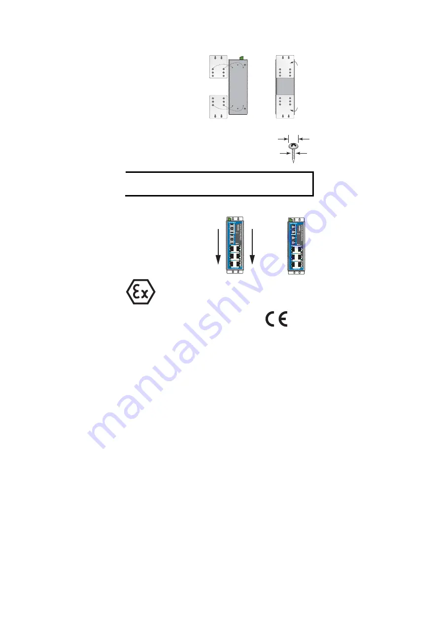
Wall Mounting (optional)
For some applications, you will find it convenient to mount the EDS on the
wall, as illustrated below.
STEP 1
:
Remove the aluminum DIN-rail
attachment plate from the
EDS’s rear panel, and then
attach the wall mount plates, as
shown in the diagram below.
⇒
top
plate
bottom
plate
STEP 2
:
Mounting the EDS on the wall requires 4 screws. Use the
switch, with wall mount plates attached, as a guide to mark
the correct locations of the 4 screws. The heads of the
screws should be less than 6.0 mm in diameter, and the
shafts should be less than 3.5 mm in diameter, as shown in
the figure at the right.
6.0 mm
3.5 mm
NOTE
Before tightening screws into the wall, make sure the screw head and
shank size are suitable by inserting the screw into one of the keyhole-
shaped apertures of the Wall Mounting Plates.
Do not screw the screws in all the way—leave about 2 mm to allow room for
sliding the wall mount panel between the wall and the screws.
STEP 3
:
Once the screws are fixed in the
wall, insert the four screw heads
through the large parts of the
keyhole-shaped apertures, and then
slide the EDS downwards, as
indicated. Tighten the four screws
for added stability.
⇒
II 3G
ATEX
Information
1.
Certification number DEMKO 09 ATEX 0812123X
2.
Ambient range (-40
°
C
≤
Tamb
≤
75
°
C)
3.
Certification string (Ex nC nL IIC T4)
4.
Standards covered ( EN60079-0:2006, EN60079-15:2005)
5.
The conditions of safe usage:
y
The Ethernet Communication Devices are to be mounted in an IP54
enclosure and used in an area of not more than pollution degree 2 as
defined by IEC60664-1.
y
A 4mm2 conductor must be used when connection to the external
grounding screw is utilized.
y
Conductors suitable for use in an ambient temperature of 93
°
C must be
used for the Power Supply Terminal.
Provisions shall be made to
prevent the rated voltage being exceeded by the transient disturbances
of more than 40%.


