background image

DA-681C Series HW UM 

Hardware Installation 


2-7 

Connecting USB Devices 

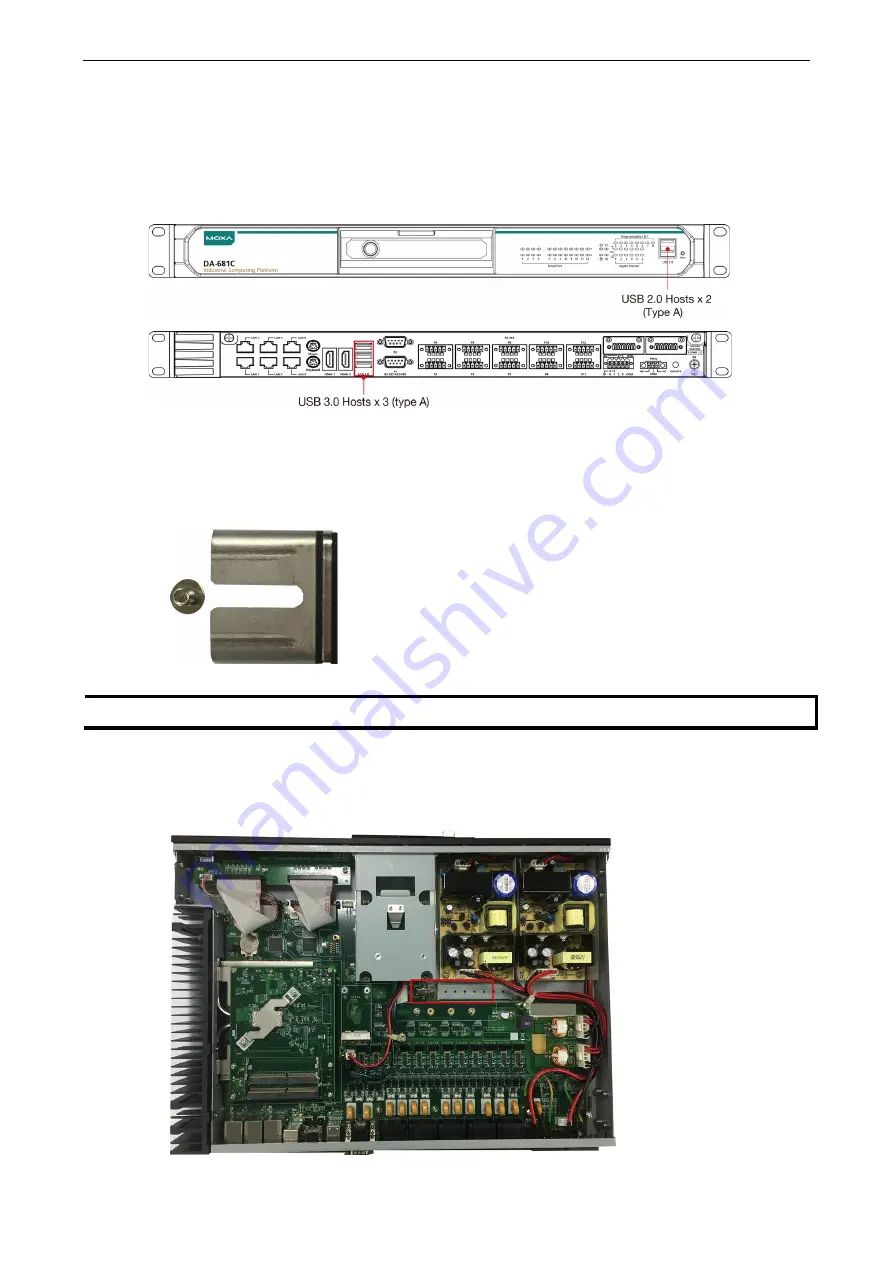
The DA-681C comes with 2 USB 2.0 ports on the front panel and 3 USB 3.0 ports on the rear panel. The 
USB ports can be used to connect to other peripherals, such as flash drives, for expanding the system’s 
storage capacity. In addition, both USB ports support system boot up, which can be activated by modifying 
the BIOS settings. See “

Chapter 3 BIOS Setup”

 for details. 


Installing a USB Dongle Kit 

You can use a USB dongle kit to secure your USB dongle inside your DA-681C computer. 

The USB dongle kit includes a USB plate and a screw. 


NOTE 

The USB dongle kit is an optional accessory that can be purchased separately. 


To install a USB dongle kit, do the following: 

1.


Power off the DA-681C computer and remove the top cover of the computer.   

2.


Find the location of the USB slot. 


Содержание DA-681C Series

Страница 1: ...DA 681C Series Embedded Computer User s Manual Version 1 0 December 2019 www moxa com product 2019 Moxa Inc All rights reserved ...

Страница 2: ... changes to this manual or to the products and or the programs described in this manual at any time Information provided in this manual is intended to be accurate and reliable However Moxa assumes no responsibility for its use or for any infringements on the rights of third parties that may result from its use This product might include unintentional technical or typographical errors Changes are p...

Страница 3: ...1 Installing SATA Hard Disks 2 12 3 BIOS Setup 3 1 Entering the BIOS Setup 3 2 Main Page 3 3 Advanced Settings 3 4 Boot Configuration 3 5 SATA Configuration 3 5 Intel Rapid Storage Technology 3 7 CPU Configuration 3 8 Intel Active Management Technology Support 3 9 Video Configuration 3 10 Chipset Configuration 3 11 SIO ITE8786E 3 12 Security Settings 3 14 Current TPM Device 3 14 TPM State 3 14 Cle...

Страница 4: ...Upgrading the BIOS 3 20 A Safety Installation Instructions A 1 ...

Страница 5: ... manual covers hardware installation connector interfaces and BIOS setup of the DA 681C For software configuration and management please refer to the user s manual for your operating system The following topics are covered in this chapter Overview Model Descriptions and Package Checklist Appearance Dimensions Features Hardware Block Diagram DA 681C Basic System Hardware Specifications ...

Страница 6: ...el Descriptions and Package Checklist The DA 681C Series includes the following models DA 681C KL1 H T Intel Celeron 3965U 2C 2T 2 2 GHz CPU with 2 HDMIs 6 Gigabit LAN ports 2 RS 232 422 485 3 in 1 serial ports 2 PS 2 interfaces 6 DIs 2DOs 1 mSATA 2 SATA 6 USB ports without RAM mSATA and OS single power 40 to 70 C operating temperature DA 681C KL1 HH T Intel Celeron 3965U 2C 2T 2 2 GHz CPU with 2 ...

Страница 7: ...EEE 1613 and IEC 60255 compliance for power substation automation systems 7th Generation Intel Core or Intel Celeron Processor Built in DDR4 memory slot up to 32 GB capacity One hot swappable 2 5 inch HDD or SSD storage expansion trays Redundant power supply 100 to 240 VAC VDC EN 50121 4 compliant for railway wayside applications ...

Страница 8: ...DA 681C Series HW UM Introduction 1 4 Hardware Block Diagram DA 681C Basic System Hardware Specifications NOTE The latest specifications for Moxa s products can be found at https moxa com ...

Страница 9: ...ime to application development This chapter describes the hardware installation and connector interfaces of the DA 681C embedded computers The following topics are covered in this chapter Installing Rack mounting Ears Wiring Requirements Connecting the Power Wiring the Power Inputs Grounding the Chassis Power Wiring Methods Reset Button LED Connecting to Displays Connecting USB Devices Installing ...

Страница 10: ... NOTE The two rack mounting ears are not identical Refer to the diagram above to identify the left rack mounting ear and the right rack mounting ear and ensure that you use them correctly to mount the computer Follow the instructions below to install the computer 1 Attach the left rack mounting ear to the left side of the DA 681C computer and fasten the four screws tightly 2 Attach the other rack ...

Страница 11: ...t signal characteristics should be routed separately ATTENTION Safety First Be sure to disconnect the power cord before installing and or wiring your device Electrical Current Caution Calculate the maximum possible current in each power wire and common wire Observe all electrical codes dictating the maximum current allowable for each wire size If the current goes above the maximum rating the wirin...

Страница 12: ...Inputs Refer to the following illustration and table for details on wiring the power inputs to the DA 681C computer The table uses the reference numbers in the diagram to identify the lines in the terminal blocks Number Description Note 1 Power Line PWR Line is connected to the Line L terminal for the AC power source Power Positive PWR Positive is connected to the terminal for the DC power source ...

Страница 13: ...ective earthing conductor for example by means of a power cord connected to a socket outlet with earthing connection Power Wiring Methods The DA 681C comes with single or dual power inputs with both AC and DC power sources supported Refer to the following diagrams for details on the wiring methods that can be used ATTENTION This equipment must be installed according to the applicable country s wir...

Страница 14: ...table LED Color Description Power Green Power is on Off No power input Storage Yellow Blinking Data is being written to or read from the storage unit Off Storage unit is idle Power 1 Failure Off The 1st power supply is on Red Error in the 1st power supply Power 2 Failure Off The 2nd power supply is on Red Error in the 2nd power supply Gigabit LAN LEDs 1 to 6 Green 100 Mbps Ethernet mode Orange 100...

Страница 15: ...s support system boot up which can be activated by modifying the BIOS settings See Chapter 3 BIOS Setup for details Installing a USB Dongle Kit You can use a USB dongle kit to secure your USB dongle inside your DA 681C computer The USB dongle kit includes a USB plate and a screw NOTE The USB dongle kit is an optional accessory that can be purchased separately To install a USB dongle kit do the fol...

Страница 16: ... 2 interfaces you can directly connect a keyboard and a mouse using these connectors Serial Ports The DA 681C comes with 2 software selectable RS 232 422 485 serial ports P1 and P2 with DB9 connectors which are located on the rear panel Pin RS 232 RS 422 RS 485 4 wire RS 485 2 wire 1 DCD TxDA TxDA 2 RxD TxDB TxDB 3 TxD RxDB RxDB DataB 4 DTR RxDA RxDA DataA 5 GND GND GND GND 6 DSR 7 RTS 8 CTS In ad...

Страница 17: ...he following figure and table for the pin sequence and definitions Pin 100 Mbps 1000 Mbps 1 Tx TRD 0 2 Tx TRD 0 3 Rx TRD 1 4 TRD 2 5 TRD 2 6 Rx TRD 1 7 TRD 3 8 TRD 3 Digital Inputs Digital Outputs The DA 681C is provided with six digital inputs and two digital outputs in a terminal block Refer to the following figure for the location of the DI and DO connectors For pin definitions and wiring metho...

Страница 18: ...the relay output connectors Upgrading the Memory Module The DA 681C embedded computer supports 2 DDR4 2133 SODIMM modules for up to 32 GB of memory 2 slots each with 16 GB capacity To upgrade the SDRAM memory module follow these instructions 1 Disconnect the DA 681C from its power source 2 Unfasten the screws on the back of the computer and then remove the top cover 3 Find the location of the SDRA...

Страница 19: ...ule is already installed in the slot push the two fasteners to free the module and then remove the module 5 Replace the top cover of the computer and fasten the screws Installing an mSATA Storage Card The DA 681C embedded computer comes with an mSATA slot To insert an mSATA storage card follow these instructions 1 Disconnect the DA 681C from its power source 2 Unfasten the screws on the back of th...

Страница 20: ...ay functions for the mSATA storage card You must disconnect the power source to the computer before inserting or removing the mSATA storage card Installing SATA Hard Disks The DA 681C comes with one SATA slot that allows users to install a 2 5 SATA HDD SSD Follow these steps to install a SATA disk 1 Unfasten the screw on the storage slot cover and pull down the cover to access the storage tray 2 P...

Страница 21: ...ement around to access the screws on the rear side of the tray Fasten the four screws to secure the SATA disk to the tray as indicated in the diagram below 5 Insert the storage tray back into the storage slot Ensure that the tray is inserted correctly into the rails of the storage slot and the tray slide smoothly inside the slot 6 Slide the storage slot cover back and fasten the screws to secure i...

Страница 22: ...Boot Configuration SATA Configuration Intel Rapid Storage Technology CPU Configuration Intel Active Management Technology Support Video Configuration Chipset Configuration SIO ITE8786E Security Settings Current TPM Device TPM State Clear TPM Set Supervisor Password Power Settings Wake on LAN Auto Wake on S5 Power On USB3 Rear Power On USB2 Front Power On USB2 Internal PS 2 Keyboard Power Up Boot S...

Страница 23: ...ement Enter the device configuration menu Boot From File Select the UEFI boot up file Setup Utility Enter the BIOS configuration menu Intel Management Engine BIOS Extension Enter the AMT configuration menu Select F2 to enter the BIOS configuration When you enter Setup Utility a basic description of each function key is listed at the bottom of the screen F1 F5 F6 F9 F10 General Help Change Values S...

Страница 24: ...en you enter the Setup Utility option as shown in the following figure NOTE The Processor Type information will vary depending on the computer model that you have purchased Main Page The Main page displays basic system hardware information such as model name BIOS version and CPU type ...

Страница 25: ...C Series HW UM BIOS Setup 3 4 Advanced Settings Select the Advanced tab in the BIOS setup utility to open the advanced features screen NOTE Active Management Technology is not supported in KL1 and KL3 models ...

Страница 26: ...OS Setup 3 5 Boot Configuration This item allows users to configure the default value of Numlock Options On default Off SATA Configuration The host drive controller can be configured for AHCI default or Intel RST Premium mode ...

Страница 27: ... 681C has three SATA interfaces which support RAID levels 0 1 5 and Recovery Recovery utilizes RAID 1 mirroring functionality to copy data from a designated master drive to a designated recovery drive The master drive data can be copied to the recovery drive either continuously or on request When using the continuous update policy changes made to the data on the master drive while the system is no...

Страница 28: ...chnology This option allows users to configure the Intel Rapid Storage Technology To configure the Intel Rapid Storage Technology settings select the Device Management option when setting the Intel RST Premium mode or saving changes and rebooting the computer ...

Страница 29: ...DA 681C Series HW UM BIOS Setup 3 8 CPU Configuration ...

Страница 30: ...ocessor throughput improving overall performance on threaded software Options Disabled Enabled default NOTE Hyper Threading is not supported in KL1 models Intel Active Management Technology Support This option allows you to configure the Intel Active Management Technology NOTE Intel Active Management Technology is not supported in KL1 and KL3 models ME Unconfig on RTC Clear State Disabling this op...

Страница 31: ...ult 36M 40M 44M 48M 52M 56M 60M 64M DVMT The amount of video memory your computer has is dependent on the amount of pre allocated memory set for your system plus the Dynamic Video Memory Technology DVMT DVMT dynamically allocates system memory for use as video memory creating the most efficient use of available resources for maximum 2D 3D graphics performance DVMT Total Gfx Mem This option allows ...

Страница 32: ... Power Failure This option allows you to enable disable the computer from automatically powering up after system power is re enabled Options ON default OFF Last State DO 0 Level This option allows users to set the DO 0 level Options High default Low DO 1 Level This option allows users to set the DO 1 level Options High default Low ...

Страница 33: ...DA 681C Series HW UM BIOS Setup 3 12 SIO ITE8786E This option allows users to configure serial port settings ...

Страница 34: ...DA 681C Series HW UM BIOS Setup 3 13 Hardware Monitor This option allows users to view stats on the computer such as CPU and system temperature voltage levels and other chipset information ...

Страница 35: ...uire the supervisor password and user password Current TPM Device This item indicates if the system has a TPM module configured and provides information on its type TPM State This item allows users to view the current TPM settings Clear TPM This item allows users to remove all TPM context associated with a specific owner ...

Страница 36: ...select the Set Supervisor Password option enter the password and re confirm the password To delete the password select the Set Supervisor Password option and enter the old password leave the new password fields blank and then press enter After setting the supervisor password users can choose when the input password screen will pop up ...

Страница 37: ...ns Enabled default Disabled Auto Wake on S5 This option allows you to configure the computer to wake from S5 status S5 stands for Soft Off where the PSU remains engaged but power to all other parts of the system is cut Auto wake on S5 schedules a soft reboot at certain periodic times that may be specified in the BIOS Options Disabled default By Every Day user specifies a regular daily time when th...

Страница 38: ...t PS 2 Keyboard Power Up This option allows users to press CTRL P to wake up the system that the PSU remains engaged with power to all other parts of the system is remains cut off Options Disabled default Enabled Boot Settings The Boot page includes configuration settings for the boot up process NOTE If you have not added any storage to your computer you will not see the EFI option Boot Type This ...

Страница 39: ...network This option allows users to start PXE over IPv4 or IPv6 Options Disabled default UEFI IPv4 UEFI IPv6 UEFI IPv4 IPv6 USB Boot Used to enable or disable boot up from USB devices Options Enabled Default Disabled Timeout This option allows users to set the number of seconds that the firmware will wait before booting the system with the default boot selection EFI This option allows users to sel...

Страница 40: ...ght have been made to the BIOS Options Yes default No Load Optimal Defaults This option allows you to revert to the factory default BIOS values Options Yes default No Load Custom Defaults This option allows you to load custom default values for the BIOS settings Options Yes default No Save Custom Defaults This option allows you to save the current BIOS values as a custom default that may be revert...

Страница 41: ...strongly recommend that you contact the Moxa technical support team for assistance to obtain all the necessary tools and the most current information before attempting to upgrade the BIOS on any Moxa device Step 1 Create a Bootable USB Disk Before upgrading the BIOS you must create a bootable USB drive for the system 1 Search for format and select Create and format hard disk partitions ...

Страница 42: ...ick OK to start formatting the USB disk Step 2 Prepare the Upgrade File You must use the BIOS upgrade installation file to upgrade the BIOS Contact Moxa s technical department for assistance 1 Get the BIOS upgrade file includes an efi folder and an xxxx efi file 2 Copy the efi folder and xxxx efi file to the bootable USB disk ...

Страница 43: ...the boot device the USB device may not have a partition table Use the Windows command line tool diskpart to rebuild the partition table 2 Select the USB disk to boot from 3 In the SHELL environment console type fs0 then go to the directory where the upgrade file is located and type xxxxxx efi the name of the file is based on the upgrade file you get from Moxa 4 The upgrade program will run automat...

Страница 44: ...s more than one boot device you will see more than one fsx x represents the number of devices 6 Access each device path fsx x is the device index then type ls to view the content of the boot device until you located the upgrade file and run it ATTENTION Do NOT switch off the power supply to the computer during the BIOS upgrade since doing so may cause the system to crash ...

Страница 45: ...oom ambient temperature Therefore consideration should be given to installing the equipment in an environment compatible with the maximum ambient temperature Tma specified by the manufacturer 2 Reduced Air Flow Installation of the equipment in a rack should be such that the amount of air flow required for safe operation of the equipment is not compromised 3 Mechanical Loading Mounting of the equip...

Отзывы: