background image

- 7 - 


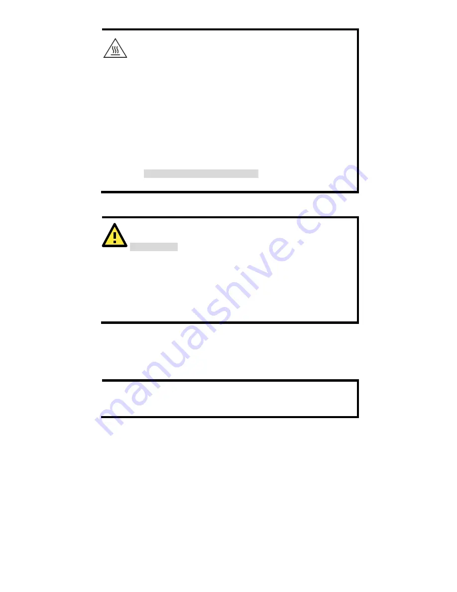
WARNING 


This equipment is intended to be used in a Restricted Access 
Location, such as a dedicated computer room where only 
authorized service personnel or users can gain access. Such 
personnel must be instructed about the fact that the metal 
chassis of the equipment is extremely hot and may cause 
burns. 


Service personnel or users have to pay special attention and 
take special precautions before handling this equipment. 


Only authorized, well-trained professionals should be allowed 
to access the Restricted Access Location. Access should be 
controlled by the authority responsible for the location with a 
lock and key or a security identity system. 


External metal parts are hot!!

 Pay special attention or use 

special protection before handling this equipment. 


Wiring Requirements 


WARNING 

Safety First!


Be sure to disconnect the power cord before installing and/or 
wiring your Moxa AWK-1137C. 
Calculate the maximum possible current in each power wire and 
common wire. Observe all electrical codes that dictate the 
maximum current allowed for each wire size. If the current goes 
above the maximum ratings, the wiring could overheat, causing 
serious damage to your equipment. 


You should also pay attention to the following items: 


Use separate paths to route wiring for power and devices. If power 
wiring and device wiring paths must cross, make sure the wires are 
perpendicular at the intersection point. 


NOTE 

Do not run signal or communications wiring and power wiring in 
the same wire conduit. To avoid interference, wires with different 
signal characteristics should be routed separately. 


You can use the type of signal transmitted through a wire to 
determine which wires should be kept separate. The rule of thumb is 
that wiring with similar electrical characteristics can be bundled 
together. 


Keep input wiring and output wiring separate. 


It is strongly advised that you label wiring to all devices in the system 
when necessary. 


Содержание AirWorks AWK-1137C

Страница 1: ...oxa Americas Toll free 1 888 669 2872 Tel 1 714 528 6777 Fax 1 714 528 6778 Moxa China Shanghai office Toll free 800 820 5036 Tel 86 21 5258 9955 Fax 86 21 5258 5505 Moxa Europe Tel 49 89 3 70 03 99 0 Fax 49 89 3 70 03 99 99 Moxa Asia Pacific Tel 886 2 8919 1230 Fax 886 2 8919 1231 Moxa India Tel 91 80 4172 9088 Fax 91 80 4132 1045 2017 Moxa Inc All rights reserved ...

Страница 2: ...and more bandwidth The AWK 1137C can operate on either the 2 4 or the 5 GHz band and is backward compatible with existing 802 11a b g deployments Hardware Setup This section covers the hardware setup for the AWK 1137C Package Checklist Moxa s AWK 1137C is shipped with the following items If any of these items is missing or damaged please contact your customer service representative for assistance ...

Страница 3: ...tem LEDs SYS WLAN LAN1 LAN2 and SERIAL 2 LAN1 10 100 BaseT X RJ45 port 3 LAN2 10 100 BaseT X RJ45 port 4 RS 232 422 485 DB9 serial port 5 3 pin terminal block ground 6 M3 screw holes for antenna bracket 7 Antenna B RP SMA 8 Antenna A RP SMA ...

Страница 4: ... 4 9 3 pin maintenance port for engineers 10 Reset button 11 Screw holes for DIN rail mounting kit 12 Screw holes for wall mounting kit ...

Страница 5: ...e DIN rail attachment plate to the AWK 1137C make sure the stiff metal spring is situated towards the top as shown in the figures below STEP 1 Insert the top of the DIN rail into the slot just below the stiff metal spring STEP 2 Gently push the device towards the DIN rail until the DIN rail attachment unit snaps into place as shown below To remove the AWK 1137C from the DIN rail reverse steps 1 an...

Страница 6: ... and the shafts should be less than 3 5 mm in diameter as shown in the figure on the right Do not drive the screws in all the way leave a space of about 2 mm to allow room for sliding the wall mounting panel between the wall and the screws NOTE Test the screw head and shank size by inserting the screws into one of the keyhole shaped apertures of the wall mounting plates before they are fixed to th...

Страница 7: ...nd or wiring your Moxa AWK 1137C Calculate the maximum possible current in each power wire and common wire Observe all electrical codes that dictate the maximum current allowed for each wire size If the current goes above the maximum ratings the wiring could overheat causing serious damage to your equipment You should also pay attention to the following items Use separate paths to route wiring for...

Страница 8: ...w to the grounding surface prior to connecting devices ATTENTION This product is intended to be mounted to a well grounded mounting surface such as a metal panel There must be no electrical potential difference between any two grounding points otherwise there is a risk that the device could be destroyed Installing Cable Extended Antennas for Outdoor Applications If the antenna or the AWK device is...

Страница 9: ...TEP 3 Insert the plastic terminal block connector prongs into the terminal block receptor which is located on the AWK 1137C s side panel NOTE Input Terminal Block CN1 is suitable for wire size range of 12 28 AWG 3 31 0 0804 mm and a torque value of 4 5 lb in 0 51 Nm ATTENTION If the AWK 1137C is connected to a motor or other similar type of equipment be sure to use power isolation protection Befor...

Страница 10: ...T X ports located on the AWK 1137C s front panel are used to connect to Ethernet enabled devices The pinouts for both the MDI NIC type and MDI X HUB switch type ports as shown below MDI Port Pinouts MDI X Port Pinouts 8 pin RJ45 Pin Signal 1 Tx 2 Tx 3 Rx 6 Rx Pin Signal 1 Rx 2 Rx 3 Tx 6 Tx RS 232 422 485 Serial Port The AWK 1137C has 1 RS 232 422 485 serial port with DB9 connector for serial to WL...

Страница 11: ... WLAN Amber On RSSI 35 WLAN interface has connected Blinking Data communication via WLAN LAN1 Green On Ethernet LAN 1 interface has connected Blinking Data communication via Ethernet LAN 1 LAN2 Green On Ethernet LAN 2 interface has connected Blinking Data communication via Ethernet LAN 2 Serial Amber Blinking Data Transmission via serial data port Specifications WLAN Interface Standards IEEE 802 1...

Страница 12: ...ncryption WPA WPA2 Personal and Enterprise IEEE 802 1X RADIUS TKIP and AES Transmission Rates 802 11b 1 2 5 5 11 Mbps 802 11a g 6 9 12 18 24 36 48 54 Mbps 802 11n 6 5 to 300 Mbps multiple rates supported Transmitter Power 802 11b Typ 26 1 5 dBm 1 Mbps Typ 26 1 5 dBm 2 Mbps Typ 26 1 5 dBm 5 5 Mbps Typ 25 1 5 dBm 11 Mbps 802 11g Typ 23 1 5 dBm 6 to 24 Mbps Typ 22 1 5 dBm 36 Mbps Typ 20 1 5 dBm 48 Mb...

Страница 13: ...02 11a 90 dBm 6 Mbps 88 dBm 9 Mbps 87 dBm 12 Mbps 85 dBm 18 Mbps 81 dBm 24 Mbps 78 dBm 36 Mbps 74 dBm 48 Mbps 73 dBm 54 Mbps 802 11n 5 GHz 69 dBm MCS7 20 MHz 70 dBm MCS15 20 MHz 64 dBm MCS7 40 MHz 66 dBm MCS15 40 MHz Protocol Support General Protocols Proxy ARP DNS HTTP HTTPS IP ICMP SNTP TCP UDP RADIUS SNMP DHCP VLAN Interface Default Antennas 2 dual band omni directional antennas 1 8 dBi RP SMA ...

Страница 14: ...2 kV Signal 1 kV IEC 61000 4 5 Surge Power 2 kV Signal 1 kV IEC 61000 4 6 CS 10 V IEC 61000 4 8 Radio EN 301 489 1 17 EN 300 328 EN 301 893 MIC FCC ID SLE 1137C WPC ANATEL KC RCM SRRC Note Check Moxa s website for the most up to date certification status Reliability MTBF 1 125 942 hrs Warranty Warranty Period 5 years Details See www moxa com support warranty aspx ATTENTION The AWK 1137C is NOT a p...

Страница 15: ...terminated by either an antenna or a terminator We strongly recommend using resistive terminators for terminating the unused antenna ports Federal Communications Commission Interference Statement This equipment has been tested and found to comply with the limits for a Class B digital device pursuant to part 15 of the FCC Rules These limits are designed to provide reasonable protection against harm...

Страница 16: ... listed below with the maximum permissible gain and required antenna impedance for each antenna type indicated Antenna types not included in this list having a gain greater than the maximum gain indicated for that type are strictly prohibited for use with this device Software Setup This section covers the software setup for AWK models in general How to Access the AWK Before installing the AWK devi...

Страница 17: ...Default Username admin Default Password moxa Click the Login button to access the homepage of the AWK device First Time Quick Configuration After successfully accessing the AWK refer to the appropriate subsection below to quickly set up a wireless network NOTE Ensure that there are no IP address conflicts when you configure more than one AWK on the same subnet Point to Multipoint Scenario AP Clien...

Страница 18: ...ence For the Channel setting we recommend that you choose a channel other than the default channel to avoid interference Click Submit to apply the changes and restart the AWK in AP mode to complete the configuration process Configuring the AWK as a Client Step 1 Set the operation mode of the AWK to Client mode Go to Wireless LAN Setup Operation Mode set the operation mode to Client and then click ...

Страница 19: ...Point to Point Scenario Master slave mode Configuring the AWK as a Master Step 1 Set the operation mode of the AWK to Master mode Go to Wireless LAN Setup Operation Mode set the operation mode to Master and then click Submit to apply the change Step 2 Set up your own SSID Go to Wireless LAN Setup WLAN Basic WLAN Setup and click Edit to set the SSID Step 3 On the Wireless LAN Setup WLAN Basic WLAN ...

Страница 20: ...reless LAN Setup WLAN Basic WLAN Setup and click Site Survey to select an existing SSID or directly enter an existing SSID in the text field Step 3 Set the RF type for the AWK On the Wireless LAN Setup WLAN Basic WLAN Setup page edit the RF type setting Click Submit to apply the changes and restart the AWK in slave mode to complete the configuration process ...

Отзывы: