6
TRIM RING INSTALLATION:
Note:
This page only covers special installation considerations for thick trim ring installation. If
the video monitor is to be installed in a vehicle with the thick trim ring, it may need to be trimmed
to fit the contour of the vehicle Head liner.
Note:
The trim rings supplied with this unit are not designed to be trimmed.
1)
In this installation, the video monitor is mounted directly to the overhead cross-member in
the roof using the mounting screw bosses. These screw bosses should contact the cross-
member directly (i.e.: no gap between the screw boss and the roof structure). Also, be sure
that the screws do not pierce the outer roof skin when fully fastened to the cross-member.
The trim ring is attached to the video monitor using the perimeter screw bosses. It is
important that the screws used in this installation are not over tightened, and that the video
monitor and trim ring are mounted in such a way that the assembly does not distort (or
bend) when the mounting screws are tightened. An alternate method is to use the
mounting bracket. First secure the mounting bracket to the cross-member, then screw the
monitor into the mounting bracket. See the drawing in this manual.
2)
It is best to mount the video monitor to the roof structure without the trim ring first. There
should be a gap between the headliner and the outer flange of the video monitor. The trim
ring should be cut to fill this gap. Apply masking tape to the outer surface of the trim ring in
the areas where the cut will be made.
3)
Mark the cut to follow the necessary contour of the roof. The suggested method of marking
is as follows:
A)
First mark the narrowest point of the trim ring on the masking tape. Be careful to
consider not only vertical location, but fore-aft location.
B)
Using the handle of a screwdriver, make a “transfer marking tool”. See diagram
below. Place the tool against the roof and the marker against the masking tape on the
trim ring. Trace the cut to be made around the entire perimeter of the trim ring.
C)
Cut the trim ring using a sharp utility knife or shears. Make the cut in several passes
over the marked line, each time cutting a little deeper. It is not necessary to cut
completely through the plastic, the cut only need be over 50% of the wall thickness of
the plastic. By bending the cut back and forth several times, the plastic will break
cleanly at the cut.
D)
Check the fit of the trimmed console and make any minor adjustments necessary.
4)
The trim ring can be painted or covered with a material that matches the head liner before
assembling the trim ring to video monitor.
5)
The finished trim ring should be attached to the video monitor, then attach the assembly to
the roof.
Tape marker to screwdriver.
Starting at your mark for the
lowest point, trace the contour of the roof
Lowest point mark
Cut line
Headliner
Содержание MMD11 A
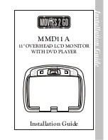
Страница 1: ...Installation Guide MMD11 A 11 OVERHEAD LCD MONITOR WITH DVD PLAYER...
Страница 8: ...8 MMD11 A Figure A AV1...
Страница 11: ......
Страница 12: ...128 8653 2009 Audiovox Electronics Corp 150 Marcus Blvd Hauppauge NY 11788...


