9/19
NT 1003-E00 09.12 AK O - AK I e
4. OPENING THE PUMP TO INSPECT
THE CYLINDER/PISTON AND BUSHINGS (continued)
Bypass fastening
For the SEALS refer to
the specified drawing
Serial Nbr
4.1 Necessary tools
• 7 - 13 - 17 - 30 open-end spanner
• 10 - 13 - 19 socket spanner
• adjustable spanner
• 1 plastic mallet
• 1 flat screwdriver
• 1 tube for assembling the bearings
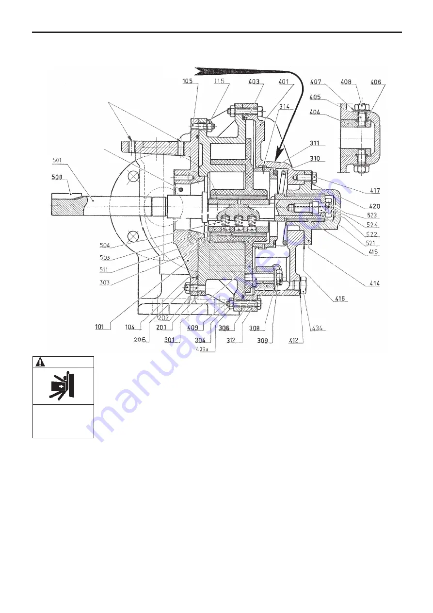
4.2 Removing the front cover
Unscrew the bolts
409
and nuts
409a
securing the front cover.
Remove the front cover
401
by progressively separating
it from the pump body. Remove the seal
403
and check its
condition. Be prepared to replace it if necessary. Check
the condition of the bushing
415
. Replace it if the wear
limits have been reached (see Instructions 1003-P00).
4.3 Removing the piston and cylinder
Remove the sleeve
521
by using the nut
523
to release it.
Extract the piston
301
from the cylinder
201
(you may
have to use a lever to separate the piston from the cylin-
der. Be very cautious not damaging the piston or the cylin-
der). Examine the condition of the piston
301
and replace
it if the wear limits have been reached (see § MAINTE-
NANCE). Examine the condition of the piston bushing
303
and replace it if the wear limits have been reached (see
Instructions 1003-P00).
To dismantle the cylinder, remove the nuts
115
. Separate
the cylinder from the main body
101
and remove the seal
104
to check its condition. Replace it if necessary.
Examine the condition of the cylinder and replace it if its
wear limits have been reached (see § MAINTENANCE).
The pumping characteristics demand a cylinder/piston
with matching dimensions. Consequently, changing the
cylinder or piston requires the replacement of both the
cylinder and the piston.
4.4 Assembly of the cylinder, piston and
front cover
Assembly is done in the reverse order to the dismantling.
BE CAREFUL WITH THE WEIGHT OF
THE PARTS WHEN THEY ARE BEING
REMOVED.
WARNING
The weight ot the parts can
be dangerous and may
provoke bodily injuries or
material damages.


